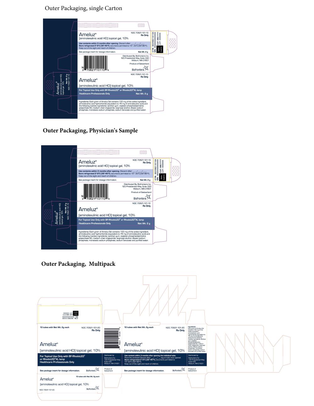
Label: AMELUZ- aminolevulinic acid hydrochloride gel
-
NDC Code(s):
70621-101-01,
70621-101-03,
70621-101-10,
70621-101-20, view more70621-101-30
- Packager: Biofrontera Inc.
- Category: HUMAN PRESCRIPTION DRUG LABEL
- DEA Schedule: None
- Marketing Status: New Drug Application
Drug Label Information
Updated April 23, 2024
If you are a consumer or patient please visit this version.
- Download DRUG LABEL INFO: PDF XML
- Official Label (Printer Friendly)
-
HIGHLIGHTS OF PRESCRIBING INFORMATION
These highlights do not include all the information needed to use AMELUZ safely and effectively. See full prescribing information for AMELUZ.
AMELUZ® (aminolevulinic acid hydrochloride) topical gel, 10%.
Initial U.S. Approval: 1999RECENT MAJOR CHANGES
Dosage and Administration, Dosage and Administration Instructions (2.2) 3/2024
INDICATIONS AND USAGE
AMELUZ, a porphyrin precursor, in combination with photodynamic therapy using BF-RhodoLED or RhodoLED XL lamp, is indicated for the lesion-directed and field-directed treatment of actinic keratoses of mild-to-moderate severity on the face and scalp (1).
DOSAGE AND ADMINISTRATION
- Administer AMELUZ only by a health care provider (2.1).
- AMELUZ is for topical use only (2.1).
- Photodynamic therapy with AMELUZ involves preparation of lesions, application of the product, occlusion and illumination with BF-RhodoLED or RhodoLED XL lamp (2.2).
- Retreat lesions that have not completely resolved 3 months after the initial treatment (2.1).
- See BF-RhodoLED or RhodoLED XL user manual for detailed lamp safety and operating instructions (2.1).
DOSAGE FORMS AND STRENGTHS
Gel: 10% (3).
CONTRAINDICATIONS
WARNINGS AND PRECAUTIONS
- Hypersensitivity reactions have been reported with the use of AMELUZ prior to photodynamic therapy (PDT). AMELUZ should be washed off and appropriate therapy instituted (5.1).
- Transient Amnestic Episodes have been reported with use of AMELUZ in combination with PDT. If patients experience amnesia or confusion, discontinue treatment and contact healthcare provider (5.2).
- Risk of Eye Injury: Patients and healthcare providers must wear protective eyewear before operating BF-RhodoLED or RhodoLED XL lamp (5.3).
- Photosensitivity: Protect treated lesions from sunlight exposure for 48 hours post treatment (5.4).
- Risk of Bleeding: Special care should be taken to avoid bleeding during lesion preparation in patients with inherited or acquired coagulation disorders (5.5).
- Ophthalmic Adverse Reactions: Avoid direct contact of AMELUZ with the eyes (5.6).
- Mucous Membrane Irritation: Avoid direct contact of AMELUZ with the mucous membranes (5.7).
ADVERSE REACTIONS
Most common adverse reactions (≥10%) were application site erythema, pain/burning, irritation, edema, pruritus, exfoliation, scab, induration, and vesicles (6.1).
To report SUSPECTED ADVERSE REACTIONS, contact Biofrontera Inc. at 1-844-829-7434 or FDA at 1-800-332-1088 or www.fda.gov/medwatch.
DRUG INTERACTIONS
Concomitant use of the following medications may enhance the phototoxic reaction to photodynamic therapy: St. John’s wort, griseofulvin, thiazide diuretics, sulfonylureas, phenothiazines, sulphonamides, quinolones, and tetracyclines (7).
See 17 for PATIENT COUNSELING INFORMATION.
Revised: 4/2024
-
Table of Contents
FULL PRESCRIBING INFORMATION: CONTENTS*
1. INDICATIONS AND USAGE
2. DOSAGE AND ADMINISTRATION
2.1 Important Administration Information
2.2 Dosage and Administration Instructions
3. DOSAGE FORMS AND STRENGTHS
4. CONTRAINDICATIONS
5. WARNINGS AND PRECAUTIONS
5.1 Hypersensitivity
5.2 Transient Amnestic Episodes
5.3 Risk of BF-RhodoLED or RhodoLED XL Lamp Induced Eye Injury
5.4 Increased Photosensitivity
5.5 Risk of Bleeding in Patients with Coagulation Disorders
5.6 Ophthalmic Adverse Reactions
5.7 Risk of Mucous Membrane Irritation
6. ADVERSE REACTIONS
6.1 Clinical Trial Experience
6.2 Postmarketing Experience
7. DRUG INTERACTIONS
8. USE IN SPECIFIC POPULATIONS
8.1 Pregnancy
8.2 Lactation
8.4 Pediatric Use
8.5 Geriatric Use
11. DESCRIPTION
12. CLINICAL PHARMACOLOGY
12.1 Mechanism of Action
12.2 Pharmacodynamics
12.3 Pharmacokinetics
13. NONCLINICAL TOXICOLOGY
13.1 Carcinogenesis, Mutagenesis, Impairment of Fertility
14. CLINICAL STUDIES
16. HOW SUPPLIED/STORAGE AND HANDLING
17. PATIENT COUNSELING INFORMATION
Hypersensitivity
Transient amnestic episodes
Photosensitivity
Common adverse reactions
- *
- Sections or subsections omitted from the full prescribing information are not listed.
- 1. INDICATIONS AND USAGE
-
2. DOSAGE AND ADMINISTRATION
2.1 Important Administration Information
AMELUZ, in conjunction with lesion preparation, is only to be administered by a health care provider.
AMELUZ is for topical use only. Not for ophthalmic, oral, or intravaginal use.
Treat single lesions or an entire field affected by multiple lesions with AMELUZ, in combination with red light photodynamic therapy (PDT). PDT requires administration of both AMELUZ and BF-RhodoLED or RhodoLED XL light. Retreat lesions that have not completely resolved after 3 months after the initial treatment.
Refer to BF-RhodoLED or RhodoLED XL user manual for detailed lamp safety and operating instructions. Both patient and medical personnel conducting the PDT should adhere to all safety instructions.
2.2 Dosage and Administration Instructions
PDT is a multi-stage process:
Step 1. Preparation of Lesions
Before applying AMELUZ, carefully wipe all lesions with an ethanol or isopropanol-soaked cotton pad to ensure degreasing of the skin.
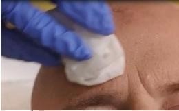 Figure 1A: Degreasing the skin
Thereafter, remove any scaling and crusts and gently roughen all lesion surfaces, taking care to avoid bleeding.
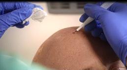 Figure 1B: Removal of scales and crust
Step 2. Application of AMELUZ
Use glove protected fingertips or a spatula to apply AMELUZ. Apply gel approximately 1 mm thick and include approximately 5 mm of the surrounding skin. Use sufficient amount of gel to cover the single lesions or if multiple lesions, the entire area. Application area should not exceed 20 cm2 and no more than 2 grams of AMELUZ (one tube) should be used at one time. The gel can be applied to healthy skin around the lesions. Avoid application near mucous membranes such as the eyes, nostrils, mouth, and ears (keep a distance of 1 cm from these areas). In case of accidental contact with these areas, thoroughly rinse with water. Allow the gel to dry for approximately 10 minutes before applying occlusive dressing.
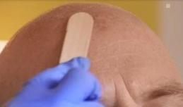 Figure 2: Drug application
Step 3. Occlusion for 3 Hours
Cover the area where the gel has been applied with a light-blocking, occlusive dressing. Following 3 hours of occlusion, remove the dressing and wipe off any remaining gel.
 Figure 3: Occlusion
Step 4. Illumination with Red Light
During illumination, patient and medical personnel need to wear suitable protective eyewear.
Immediately after removing occlusion and any remaining gel, illuminate the treatment area with the BF-RhodoLED or RhodoLED XL lamp. BF-RhodoLED and RhodoLED XL lamps are red light sources with a narrow spectrum around 635 nm that deliver a light dose of approximately 37 J/cm2. Calibration by the operator is not needed; the illumination time is calculated automatically.
Either the BF-RhodoLED or RhodoLED XL lamp can be used:
- BF-RhodoLED has an effective treatment area of 6 x 16 cm when an area of 8 x 18 cm is illuminated. Position the lamp head 5-8 cm from the skin’s surface. Larger areas can be illuminated in several steps.
- RhodoLED XL has a curved configuration with an effective treatment area up to 23 x 29 cm. Position the lamp head of the RhodoLED XL 11-14 cm from the skin’s surface. This usually allows a full-face illumination with the use of 5 panels. The smallest recommended number of panels to be used are 3 adjacent panels (see chapter 8.4.6 of RhodoLED XL user manual).
Healthy untreated skin surrounding the AK lesions does not need protection during illumination.
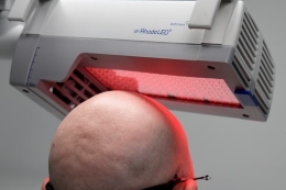 Figure 4A: Illumination with BF-RhodoLED
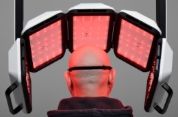 Figure 4B: Illumination with RhodoLED XL
If for any reason, the lesions cannot be illuminated within 3 hours after AMELUZ application, rinse off the gel with saline and water. For 2 days, protect the lesion sites and surrounding skin from sunlight or prolonged or intense light (e.g., tanning beds, sun lamps).
- 3. DOSAGE FORMS AND STRENGTHS
-
4. CONTRAINDICATIONS
AMELUZ is contraindicated in patients with:
- Known hypersensitivity to porphyrins.
- Known hypersensitivity to any of the components of AMELUZ, which includes soybean phosphatidylcholine [see Warnings and Precautions (5.1)].
- Porphyria. AMELUZ use may cause uncontrolled phototoxic effects [see Warnings and Precautions (5.4)].
- Photodermatoses. PDT may worsen the phototoxic or photoallergic reactions [see Warnings and Precautions (5.4)].
-
5. WARNINGS AND PRECAUTIONS
5.1 Hypersensitivity
Several cases of hypersensitivity were reported during postmarketing use of AMELUZ prior to PDT illumination [see Adverse Reactions (6.2)]. If allergic reactions occur, clean the area of skin where the product was applied and institute appropriate therapy. Inform patients and their caregivers that AMELUZ may cause hypersensitivity, potentially including severe courses (anaphylaxis).
5.2 Transient Amnestic Episodes
Transient amnestic episodes have been reported during postmarketing use of AMELUZ in combination with photodynamic therapy. Inform patients and their caregivers that AMELUZ in combination with photodynamic therapy may cause transient amnestic episodes. Advise them to contact the healthcare provider if the patient develops amnesia after treatment.
5.3 Risk of BF-RhodoLED or RhodoLED XL Lamp Induced Eye Injury
BF-RhodoLED or RhodoLED XL lamp may cause eye irritation, glare, or injury. Before operating the lamp, personnel must refer to the user manual for specific warnings, cautions, and instructions. Eye exposure to the BF-RhodoLED or RhodoLED XL light must be prevented. Protective eye equipment must be used by patient, healthcare providers and any person present during the illumination period. Avoid staring directly into the light source [see Dosage and Administration (2)].
5.4 Increased Photosensitivity
AMELUZ increases photosensitivity. Avoid sunlight, prolonged or intense light (e.g., tanning beds, sun lamps) on lesions and surrounding skin treated with AMELUZ for approximately 48 hours following treatment, whether exposed to illumination or not. Concomitant use of AMELUZ with other known photosensitizing agents may increase the risk of phototoxic reaction to PDT [see Drug Interactions (7)].
5.5 Risk of Bleeding in Patients with Coagulation Disorders
AMELUZ has not been tested on patients with inherited or acquired coagulation disorders.
Special care should be taken to avoid bleeding during lesion preparation in such patients [see Dosage and Administration (2)]. Any bleeding must be stopped before application of the gel.
-
6. ADVERSE REACTIONS
The following adverse reactions are discussed in greater detail in other sections of the labeling:
- Hypersensitivity [see Warnings and Precautions (5.1)].
- Transient Amnestic Episodes [see Warnings and Precautions (5.2)].
- Risk of BF-RhodoLED or RhodoLED XL Lamp Induced Eye Injury [see Warnings and Precautions (5.3)].
- Increased Photosensitivity [see Warnings and Precautions (5.4)].
- Risk of Bleeding in Patients with Coagulation Disorders [see Warnings and Precautions (5.5)].
- Ophthalmic Adverse Reactions [see Warnings and Precautions (5.6)].
- Risk of Mucous Membrane Irritation [see Warnings and Precautions (5.7)].
6.1 Clinical Trial Experience
Because clinical trials are conducted under widely varying conditions, adverse reaction rates observed in the clinical trials of a drug cannot be directly compared to rates in the clinical trials of another drug and may not reflect the rates observed in practice.
The clinical program for AMELUZ included three double-blind and placebo-controlled trials (Trials 1, 2, and 3), enrolling a total of 299 subjects that were treated with narrow band light. Trial subjects were adults greater than or equal to 49 years of age, and the majority had Fitzpatrick skin type I, II, or III. No subjects had Fitzpatrick skin type V or VI. Approximately 86% of subjects were male, and all subjects were Caucasian.
For all trials, the enrolled subjects had mild to moderate AKs (Olsen grade 1 and 2) with 4 to 8 lesions on the face and scalp. Overall, 87 placebo-treated subjects (n=16, n=32, n=39) and 212 AMELUZ-treated subjects (n=32, n=55, and n=125) were illuminated with BF-RhodoLED or similar narrow spectrum lamps.
Local skin reactions at the application site were observed in about 99.5% of subjects treated with AMELUZ and narrow spectrum lamps. The most frequent adverse reactions during and after PDT were application site erythema, pain, burning, irritation, edema, pruritus, exfoliation, scab, induration, and vesicles.
Most adverse reactions occurred during illumination or shortly afterwards, were generally of mild or moderate intensity, and lasted for 1 to 4 days in most cases; in some cases, however, they persisted for 1 to 2 weeks or even longer. Severe pain/burning occurred in up to 30% of subjects. In one case, the adverse reactions required interruption or discontinuation of the illumination.
The incidence of common (≥1%, <10%) and very common (≥10%) adverse reactions in randomized, multicenter trials at the application site are presented in Table 1.
Table 1: Incidence of Adverse Reactions Occurring at ≥1% of the AMELUZ Group and More Frequently than the Vehicle Group in the Actinic Keratosis Trials at the Application Site Adverse reaction
Vehicle
n=87AMELUZ
n=212Adverse reactions at the
application siteErythema
Pain/Burning
Irritation
Edema
Pruritus
Exfoliation
Scab
Induration
Vesicles
Paresthesia
Hyperalgesia
Reaction
Discomfort
Erosion
Discharge
Bleeding
Pustules
34 (39%)
26 (30%)
17 (20%)
3 (3%)
14 (16%)
4 (5%)
2 (2%)
0 (0%)
1 (1%)
2 (2%)
0 (0%)
2 (2%)
0 (0%)
0 (0%)
0 (0%)
0 (0%)
0 (0%)
195 (92%)
195 (92%)
153 (72%)
75 (35%)
72 (34%)
41 (19%)
41 (19%)
26 (12%)
25 (12%)
18 (9%)
13 (6%)
8 (4%)
7 (3%)
6 (3%)
4 (2%)
3 (1%)
3 (1%)
Common (≥1%, <10%) adverse reactions not at the application site for AMELUZ were headache, skin exfoliation, chills and eyelid edema.
Less common (≥0.1%, <1%) adverse reactions at the application site for AMELUZ were hemorrhage and swelling. The adverse reactions not at the application site were blister, feeling hot, pruritus, pyrexia, scab, nervousness, pain, petechiae, rash pustular, skin erosion and ulcer.
In a clinical trial designed to investigate the sensitization potential of aminolevulinic acid with 216 healthy subjects, 13 subjects (6%) developed allergic contact dermatitis after continuous exposure for 21 days with doses of aminolevulinic acid that were higher than doses normally used in the treatment of AK.
6.2 Postmarketing Experience
The following adverse reactions have been reported during post-approval use of AMELUZ. Because these reactions are reported voluntarily from a population of uncertain size, it is not always possible to reliably estimate their frequency or establish a causal relationship to drug exposure.
Skin and subcutaneous tissue disorders: allergic dermatitis, application site inflammation, application site discoloration.
Eye disorders: eye irritation, diplopia, ocular hyperemia, photophobia, and blurred vision.
General disorders and administration site conditions: fatigue.
Immune System disorders: hypersensitivity.
Nervous system disorders: dysaesthesia, transient amnestic episodes.
-
7. DRUG INTERACTIONS
There have been no formal studies of the interaction of AMELUZ with other drugs. It is possible that concomitant use of other known photosensitizing agents such as St. John’s wort, griseofulvin, thiazide diuretics, sulfonylureas, phenothiazines, sulphonamides, quinolones and tetracyclines may enhance the phototoxic reaction to PDT [see Warnings and Precautions (5.3)].
-
8. USE IN SPECIFIC POPULATIONS
8.1 Pregnancy
Risk Summary
There are no available data on AMELUZ use in pregnant women to inform a drug associated risk. Animal reproduction studies were not conducted with aminolevulinic acid. Systemic absorption of aminolevulinic acid in humans is negligible following topical administration of AMELUZ under maximal clinical use conditions [see Clinical Pharmacology (12.3)]. It is not expected that maternal use of AMELUZ will result in fetal exposure to the drug.
The estimated background risk of major birth defects and miscarriage for the indicated population are unknown. In the U.S. general population, the estimated background risk of major birth defects and miscarriage in clinically recognized pregnancies is 2% to 4% and 15% to 20%, respectively.
8.2 Lactation
Risk Summary
No data are available regarding the presence of aminolevulinic acid in human milk, the effects of aminolevulinic acid on the breastfed infant or on milk production. However, breastfeeding is not expected to result in exposure of the child to the drug due to the negligible systemic absorption of aminolevulinic acid in humans following topical administration of AMELUZ under maximal clinical use conditions [see Clinical Pharmacology (12.3)]. The developmental and health benefits of breastfeeding should be considered along with the mother’s clinical need for AMELUZ and any potential adverse effects on the breastfeeding child from AMELUZ or from the underlying maternal condition.
8.4 Pediatric Use
Safety and effectiveness in pediatric patients below the age of 18 have not been established. AK is not a condition generally seen in the pediatric population.
8.5 Geriatric Use
Of the 384 subjects exposed to AMELUZ in randomized, multicenter clinical trials, 83% (318/384) of the subjects were 65 years old and over. No overall differences in safety or effectiveness were observed between these subjects and younger subjects, but greater sensitivity of some older individuals cannot be ruled out.
-
11. DESCRIPTION
AMELUZ (aminolevulinic acid hydrochloride) topical gel, 10% is a non-sterile white-to-yellowish gel. The gel formulation contains a nanoemulsion.
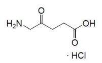
Aminolevulinic acid, a porphyrin precursor, is a white to off-white crystalline solid. It is readily soluble in water, methanol, and dimethylformamide. Its chemical name is 5-amino-4-oxo-pentanoic acid hydrochloride, molecular weight is 167.59 and molecular formula is C5H9NO3·HCl. The structural formula of aminolevulinic acid hydrochloride is represented below:
Each gram of AMELUZ contains 100 mg of aminolevulinic acid hydrochloride (equivalent to 78 mg aminolevulinic acid) as the active ingredient and the following inactive ingredients: xanthan gum, soybean phosphatidylcholine, polysorbate 80, medium-chain triglycerides, isopropyl alcohol, dibasic sodium phosphate, monobasic sodium phosphate, sodium benzoate and purified water.
-
12. CLINICAL PHARMACOLOGY
12.1 Mechanism of Action
Photoactivation following topical application of AMELUZ occurs when aminolevulinic acid (prodrug) is metabolized to protoporphyrin IX (PpIX), a photoactive compound which accumulates in the skin. When exposed to red light of a suitable wavelength and energy, PpIX is activated resulting in an excited state of porphyrin molecules. In the presence of oxygen, reactive oxygen species are formed which causes damage to cellular components, and eventually destroys the cells. AMELUZ photodynamic therapy of AK lesions utilizes photoactivation of topically applied AMELUZ resulting from BF-RhodoLED or RhodoLED XL illumination, which provides a red light of narrow spectrum and a light dose of approximately 37 J/cm2.
12.2 Pharmacodynamics
The pharmacodynamics of AMELUZ in the treatment of actinic keratosis are unknown.
12.3 Pharmacokinetics
Pharmacokinetics (PK) of aminolevulinic acid and PpIX was evaluated in a trial of 12 adult subjects with mild to moderate AK with at least 10 AK lesions on the face or forehead. A single dose of one entire tube of AMELUZ (2 grams) was applied under occlusion for 3 hours followed by PDT to a total area of 20 cm2. The mean ± SD baseline plasma aminolevulinic acid and PpIX concentrations were 20.16 ± 16.53 ng/mL and 3.27 ± 2.40 ng/mL, respectively. In most subjects, an up to 2.5-fold increase of aminolevulinic acid plasma concentrations was observed during the first 3 hours after AMELUZ application. The mean ± SD area under the concentration time curve (AUC0-t) and maximum concentration (Cmax) for baseline corrected aminolevulinic acid (n=12) were 142.83 ± 75.50 ng.h/mL and 27.19 ± 20.02 ng/mL, respectively. The median Tmax (time at which Cmax occurred) was 3 hours.
The majority (about 55%) of the PpIX concentrations were below the limit of quantification (LOQ = 1 ng/mL) and baseline corrected values were negative in all subjects except for one. The baseline corrected AUC0-t and Cmax in the single subject was 0.07 ng.h/mL and 0.29 ng/mL, respectively. PK of aminolevulinic acid and PpIX following treatment on the scalp was not evaluated.
-
13. NONCLINICAL TOXICOLOGY
13.1 Carcinogenesis, Mutagenesis, Impairment of Fertility
Long-term studies to evaluate the carcinogenic potential of AMELUZ or aminolevulinic acid have not been performed.
Aminolevulinic acid revealed no evidence of mutagenic or clastogenic potential based on the results of three in vitro genotoxicity tests (Ames assay, HPRT test in V79 cells, and Human lymphocyte chromosomal aberration assay) and one in vivo genotoxicity test (mouse micronucleus assay). These genotoxicity studies were conducted without exposure to light. There is a literature report that indicates that aminolevulinic acid may cause genotoxic effects in the presence and in the absence of activating light. These genotoxic effects are likely caused by the formation of reactive oxygen species.
Animal fertility studies have not been conducted with aminolevulinic acid because of the negligible systemic absorption of aminolevulinic acid in humans following topical administration of AMELUZ under maximal clinical use conditions.
-
14. CLINICAL STUDIES
The efficacy and safety of AMELUZ in combination with PDT using a narrow spectrum (red light lamp) source were evaluated in three randomized, multicenter trials (Trials 1, 2, and 3). Trials 2 and 3 were vehicle-controlled and double-blind. Trial 1 was double-blind with respect to vehicle and observer-blind regarding the active comparator arm. All clinical trials included a follow-up assessment after 6 and 12 months.
In these trials, 212 subjects with 4 to 8 mild to moderate AK lesions on the face/forehead and/or bald scalp were treated with AMELUZ and a narrow band spectrum lamp. Subjects ranged from 49 to 87 years of age (mean 71 years), and 92% had Fitzpatrick skin type I, II, or III. No subjects had Fitzpatrick skin type V or VI. Approximately 86% of subjects were male, and all subjects were Caucasian.
All sessions were comprised of lesion preparation to roughen the surface and remove crusts, application of AMELUZ with occlusion for 3 hours, and removal of the residual gel. Subsequently, the entire treatment area was illuminated with a narrow spectrum red light source, a lamp of either 630 nm or 633 nm and a light dose of approximately 37 J/cm2. In Trial 3, illumination was performed with BF-RhodoLED, a red light source with a narrow spectrum around 635 nm and a light dose of approximately 37 J/cm2.
In all trials, the lesions that were not completely cleared 12 weeks after the initial treatment were treated a second time with an identical regimen. In the trials, 42% (88/212) of subjects needed a second treatment.
The primary endpoint for all trials was complete clearance 12 weeks after the last PDT. The results of Trials 1, 2 and 3 are presented in Table 2.
Table 2: Complete Clearance 12 Weeks After the Last Narrow Spectrum PDT in Subjects with Actinic Keratoses AMELUZ
Vehicle Trial 1
106/125 (85%)
5/39 (13%)
Trial 2
27/32 (84%)
2/16 (13%)
Trial 3
50/55 (91%)
7/32 (22%)
Subjects who achieved complete clearance at 12 weeks after the last PDT entered a 12-month follow-up period. In the three trials, subjects who received AMELUZ with the narrowband PDT and achieved complete clearance 12 weeks after the last PDT had recurrence rates of 14%, 11%, and 25%, respectively (at 6 months) and 40%, 22%, and 37%, respectively (at 12 months).
Recurrence was defined as the percentage of subjects with at least one recurrent lesion during the 6-month or 12-month follow-up period in subjects with completely cleared lesions 12 weeks after the last PDT.
-
16. HOW SUPPLIED/STORAGE AND HANDLING
AMELUZ (aminolevulinic acid hydrochloride) topical gel, 10% is a white-to-yellowish gel. The drug product is supplied in an aluminum tube with a white, high density polyethylene (HDPE) screw cap. Each tube contains 2 g of gel.
NDC 70621-101-01 2 g tube
NDC 70621-101-10 Cardbox containing one 2 g tube
NDC 70621-101-20 Cardbox containing ten 2 g tubes
Store AMELUZ in a refrigerator, 2°C – 8°C (36°F – 46°F). Excursions permitted to 15°C – 30°C (59°F – 86°F).
After opening, AMELUZ can be stored for up to 12 weeks in a refrigerator at 2°C – 8°C (36°F – 46°F) if the tube is tightly closed.
-
17. PATIENT COUNSELING INFORMATION
Hypersensitivity
Hypersensitivity has been reported with use of AMELUZ. Inform patients and their caregivers that AMELUZ may cause hypersensitivity potentially including severe courses (anaphylaxis) [see Warnings and Precautions (5.1)].
Transient amnestic episodes
Transient amnestic episodes have been reported with use of AMELUZ in combination with photodynamic therapy. Advise patients and their families or caregivers to contact their healthcare provider if memory impairment, confusion, or disorientation is observed [see Warnings and Precautions (5.2)].
Photosensitivity
Advise patients that for approximately 48 hours following treatment to avoid exposure to sunlight, and prolonged or intense light on the treated lesion sites and surrounding skin.
Advise patients to avoid certain medications that may enhance the phototoxic reaction to PDT [see Warnings and Precautions (5.4) and Drug Interactions (7)].
Common adverse reactions
Inform patients that treatment with AMELUZ in combination with PDT may result in adverse reactions which include local skin reactions at the application site such as erythema, pain/burning, irritation, edema, pruritus, exfoliation, induration, scab, and vesicles [see Clinical Trial Experience (6.1)]
- SPL UNCLASSIFIED SECTION
- SPL UNCLASSIFIED SECTION
- SPL UNCLASSIFIED SECTION
-
INSTRUCTION FOR USE

User Manual
Manufacturer: Biofrontera Pharma GmbH
Distributor: Biofrontera Inc.
ForewordThank you for choosing the BF-RhodoLED® LED lamp for your photodynamic therapy. BF-RhodoLED® has been developed in accordance with applicable technical standards to provide high energy efficiency as well as constant light emission at the desired wavelength.
Your lamp must be installed and maintained by a qualified Biofrontera technician and used only in accordance with the instructions in this manual. You may request the latest printed version covering this model from Biofrontera at any time.
Our drug Ameluz® and medical device BF-RhodoLED® have been approved in combination for photodynamic therapy; the only approved use of our lamp is in combination with Ameluz® gel. This user manual provides important BF-RhodoLED® product details, cautions and warnings, and operating instructions. For Ameluz®, please use its US prescribing information. The Ameluz® prescribing information includes information on how to use the gel along with contraindications, warnings and precautions and dosage and administration.Thorough reading and use of both this user manual and the Ameluz® USPI is required prior to treatment.
Our combination Ameluz®/BF-RhodoLED® for photodynamic therapy is only to be used by physicians or healthcare professionals.For further questions about Ameluz®, BF-RhodoLED® or the combination therapy please contact your sales representative or Biofrontera (Ameluz-US@biofrontera.com). See contact information below or visit us at http://www.biofrontera.us.com/
Sales representative:
Name:
Tel.:
E-mail:
Biofrontera Inc.
120 Presidential Way
Suite 330
Woburn, MA 01801
USA
Phone: (844) 426-3589Warranty and Disclaimers
Please see the terms and conditions of your contract for this information.Manufacturer
Biofrontera Pharma GmbH, Hemmelrather Weg 201, 51377 Leverkusen, Germany1 Intended Use
BF-RhodoLED® is a red light emitting LED lamp which is used exclusively in combination with Ameluz® gel for lesion-directed and field-directed treatment of actinic keratoses (AKs) of mild-to-moderate severity on the face and scalp.
2 BF-RhodoLED® - General DescriptionBF-RhodoLED® is comprised of three main components, the lamp head, the easily adjustable scissor arm, and the mobile frame with castors for smooth transport. In addition, the lamp has a convenient touchscreen monitor, storage shelf, aids for positioning the lamp head and a variable speed patient fan that can be regulated throughout the treatment.
3 Warnings and Precautions
The BF-RhodoLED® has been developed for use in photodynamic therapy in combination with Ameluz® gel (excitation wavelength approx. 635 nm). Any other use or combination of use is prohibited. 
During PDT side-effects such as application site erythema, pain, irritation, edema, pruritus, exfoliation, scab, induration and vesicles may occur. For further information please see Ameluz® USPI chapter 6. 
The user manual must be read carefully prior to using the BF-RhodoLED®. 
The BF-RhodoLED® may only be used by healthcare professionals who have received adequate training in its use. 
To avoid eye irritation, glare, or injury, protective eye equipment must be used by patient, healthcare providers and any person present during the illumination period. 
Neither the BF-RhodoLED® nor the power supply unit should be exposed to excessive mechanical stress or serviced by unauthorized personnel. Assembly and servicing may only be carried out by Biofrontera qualified professionals. 
Risk of trapping fingers! The mobility of the adjustable scissor arm may be obstructed by objects placed in or near slots!
Depending on positioning, the scissor arm slots below each connecting portion of the scissor arm and to the right of the support rail can cause fingers or objects to become trapped. When transporting or adjusting the lamp please ensure that fingers or other objects are NOT placed in or near the slots (see Figure 1).

Beware of Tipping!
If the castors are in locked position, the lamp will tip over if exposed to lateral force. Leaning against the device or using it for support is not permitted.
Do not place the lamp on uneven or unstable surfaces.
Do not place heavy objects on the storage shelf (maximum load up to 8 kg) or use for sitting, leaning or pushing, as this can lead to the device tipping over.
In order to avoid the risk of electrical shock, the device may only be connected to a power supply with a grounded connection. 
Neither the BF-RhodoLED® nor its touchscreen monitor may come into contact with water as this may lead to severe damage or electrical shock (exception: cleaning with a damp cloth). 
The plexiglass plate on the lamp head may NOT be touched during or directly after treatment as, in the event of faulty operation, the maximum temperature can reach approx. 73 °C (163.4 °F).

Do not position the lamp so that it is difficult to unplug the power plug of the medical device. The lamp can only be disconnected from the supply grid by pulling the power plug.

The BF-RhodoLED® should be operated and housed indoors in areas with temperatures between 0°C and 40°C (32°F and 104°F), and relative humidity of 10 % to 90 %. 
Medical electronic devices require special precautionary measures with regard to the electro-magnetic compatibility (EMC); to avoid elect-magnetic disturbances, please do not place the device close to other electrical devices. 
There is a risk of tripping over the power cord or the lamp base. When transporting or when device is not in use, unplug and keep the power cord wound around the star knobs. 
Ensure that the touchscreen monitor is always returned to the fixture intended for this purpose, located on the storage shelf. Storing the touchscreen monitor by hanging it can lead to damage to the spiral cord and the plug fitting. 
The touchscreen monitor should not be exposed to strong external pressure or sharp objects. 
A person trained in operation of the BF-RhodoLED® must always be present during treatment. 
The device must be protected against unauthorized use.Both the maintenance and the assembly of the BF-RhodoLED® and its components (including the opening of individual components) may only be carried out by authorized personnel. In the event of servicing or assembly being carried out by any other party, Biofrontera assumes no responsibility or liability regarding the safety or use of the device. 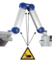
Figure 1: The scissor arm in parked position. Arrows indicate potential points where fingers can get trapped. (The appearance of devices from batches 001 to 003 slightly differs. Appearance and location of the labels remain unaltered).
4 BF-RhodoLED® Technical Description
4.1 Light Emitting Diodes (LEDs)
The light-field of the BF-RhodoLED® consists of a total of 128 LEDs and lenses (arranged in a rectangle), which emit a uniform, bundled, visible red light with a typical peak wavelength of approximately 635 nm. The half-band width of the lamp is 20 nm.
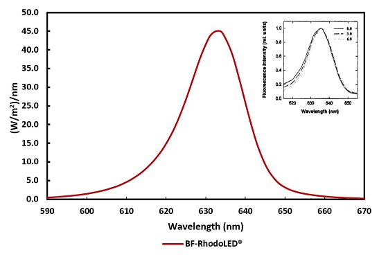
Figure 2: Typical emission spectrum of the LEDs of the BF-RhodoLED®. Insert: Fluorescence excitation spectrum of PPIX in cells 0, 3 and 6 mm below the tissue surface (Moan et al., 1996)
The BF-RhodoLED® LEDs are calibrated so that the skin being treated receives a light dosage of approximately 37 J/cm2 under the following conditions:
- Illumination time of 10 minutes
- Treatment distance of 5-8 cm (Optimum 6 cm)
The illumination area of the LED lamp is 8 x 18 cm. As the intensity decreases towards the edge of this area, the effective treatment area is reduced to 6 x 16 cm.
4.2 Lamp ComponentsThe BF-RhodoLED® LED lamp consists of the following components (Figure 3):
- Lamp head with holding bracket
- Scissor arm
- Storage shelf with control unit (touchscreen monitor)
- Mobile frame and lamp base (include support rail, castors and power supply)
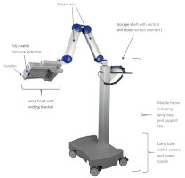
Figure 3: BF-RhodoLED® main components. (The appearance of devices from batches 001 to 003 slightly differs.)
The swivel range to the left and right of the vertical rail is +/- 24°. The lamp head can be adjusted horizontally and vertically and tilted sideways. The scissor arm with internal gas springs allows seamless adjustment of the lamp head to any position.
5 Eye ProtectionIn order to avoid eye irritation, glare or injury, protective eye equipment must be used by patient, healthcare providers and any person present during the illumination period. Do not stare into the light source! The operator and other persons present must wear protective glasses with a visible light transmission (VLT) of approximately 10%. The patient must wear eye protection such as disposable eye protection pads or eye caps with an optical density for visible light of 6 or higher. Both options are effective and comfortable for use during treatment.
Note: Eyewear is not part of the medical device. Please carefully read any accompanying usage information before using any eye protection.
In order to avoid eye irritation, glare or injury, protective eye equipment must be used by patient, healthcare providers and any person present during the illumination period.
6 BF-RhodoLED® PDT Summarized Step-by-Step InstructionsThese instructions should be used in conjunction with detailed operating instructions below (chapter 7). The section titles and numbers listed next to the instruction refer to the detailed instructions and/or descriptions that correspond with each step.
Note: Every user of the BF-RhodoLED® has to be trained in operating the device. The initial training is provided by Biofrontera during set-up of the BF-RhodoLED®. Recurrent training is not mandatory but can be provided by Biofrontera employees. Before treating a patient with Ameluz, please ensure that BF-RhodoLED® is in good working order.STEP 1) Plug in lamp. STEP 2) Turn on the lamp and wait for home screen to appear (see chapter 7.3) STEP 3) Check the proper functioning of the BF-RhodoLED®. STEP 4) Treat the affected skin area: Application, incubation and removal of the topical medication following the USPI of Ameluz®. STEP 5) Position patient comfortably and place protective eyewear on patient (see chapter 5). STEP 6) Position the lamp and adjust the lamp head over the skin area to be treated (distance 5-8 cm) (see chapter 7.5.1). STEP 7) Put on protective eyewear and make sure anyone remaining in the treatment room also wears protective eyewear (see chapter 5). STEP 8) Start treatment by pressing "Treatment" on the home screen, press "Start" on the treatment screen, and press "Start" once again in the profile screen. The illumination period of 10 minutes begins (see chapter 7.5.3).
Remind the patient to remain still throughout the illumination period.
If sound tone during treatment is activated, explain the beep sequence to the patient.
If the patient needs a break, press "Break" on the profile standard screen. To resume treatment, press "Start" on the profile standard screen (see chapter 7.5.3).
To abort the illumination, press "Stop" on the profile standard screen.
Adjust fan speed as needed by patient by pressing plus or minus 1% or 10% on the profile standard screen.
Stay with the patient at all times during the illumination period.STEP 9) At the end of the illumination period, remove patient's protective eyewear and follow further instructions in the Ameluz® USPI.
7 Detailed Operating InstructionsNote: Every user of the BF-RhodoLED® has to be trained in operating the device. The initial training is provided by Biofrontera during set-up of the BF-RhodoLED®. Recurrent training is not mandatory but can be provided by Biofrontera employees. The device must be protected against unauthorized use.

In order to avoid eye irritation, glare or injury, protective eye equipment must be used by patient, healthcare providers and any person present during the illumination period.
7.1 Transport of the lampThe transportation of the lamp shall be done when the scissor arm is completely folded. During transportation one hand shall hold on to the support rail or storage shelf while the other hand holds the scissor arm (Figure 4).
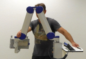
Figure 4: Transport of the lamp. (The appearance of devices from batches 001 to 003 slightly differs.)
7.2 Movement area of the scissor arm and the lamp head
The scissor arm has a swivel range of +/- 24 degrees to the left and right. The swivel range is limited by a pin at the connection between scissor arm/ support rail and scissor arm/ lamp head (Figure 5).
The lamp head can be adjusted horizontally and vertically and tilted sideways, as it has a swivel range of +/- 90 degrees in all three dimensions.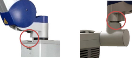
Figure 5: Limiting pins of the scissor arm and the lamp head. (The appearance of devices from batches 001 to 003 slightly differs. Appearance and location of the labels remain unaltered.)
7.3 Turning the Lamp On or Off
Note: Before turning on the lamp, the power cord must be plugged in. After connecting, the lamp can be turned on and used following the instructions below.
The on-off switch is located on the left side of the touchscreen monitor, close to its spiral cord. With the lamp plugged in, press the button to start the device.
Important: This push button can also be used to turn the lamp off. Switching off the lamp can also be done by pressing the switch off button on the touchscreen (see chapter 7.4.2 "Home Screen").
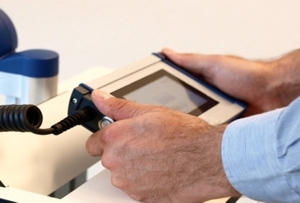
Figure 6: Touchscreen monitor
Note: The blue LED of the push button indicates that the device is in stand-by mode.
7.4 Touchscreen Monitor and MenuWhen using the touchscreen, please firmly press the center of the buttons shown on the screen to ensure it is read correctly by the software. Do not press too quickly, the input may not be read by the software. The touchscreen can be used while wearing commercially available examination gloves.
7.4.1 Start ScreenThe Biofrontera corporate logo and software version are displayed during the LED lamp operating system start-up (Figure 7). The operating system takes approximately 30 seconds to load.
Figure 7: Start screen
7.4.2 Home ScreenThe home screen appears after the operating system has loaded. From the home screen you can select "Treatment", "Settings" or "Service" (Figure 8). In the "Treatment" menu only one treatment profile "profile standard" is available. The illumination time and light intensity of this program are fixed (see 7.5.3 for further information). The "Settings" menu allows adjustment of language, time, date, audio signals and power saving settings (see 7.6 for further information). The "Service" menu may only be accessed by authorized personnel. You can turn the LED lamp off by pressing the
 button.
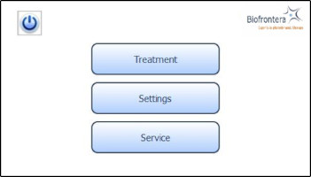
Figure 8: Home screen
7.5 Conducting a TreatmentPrior to treating a patient with Ameluz please ensure that BF-RhodoLED® is in good working order. Before starting a treatment, make sure the lamp is set-up in accordance with the operating instructions described in the following sections.
7.5.1 Distance IndicatorPosition the lamp head over the skin area to be treated at a distance of 5-8 cm. Use the adjustable distance indicator and graduated scale bar to help measure and aid in achieving the correct distance (Figure 9).
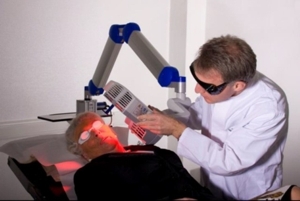
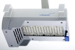
Figure 9: Positioning of the lamp head to the treated skin area
7.5.2 Adjustment Light
To further aid positioning, use the adjustment light. On the touchscreen, press the following buttons in sequence (starting in the home screen): "Treatment" (Figure 8), "Adjust" (Figure 10) and "Start Adjustment" (Figure 11). The adjustment light shows what the field of illumination will be during treatment but at a lower intensity (6x16 cm, approx. 2.4 x 6.3 inches). When finished, press "Stop adjustment" and then "Back" (Figure 11) to return to the treatment menu (Figure 10).

Figure 10: Treatment menu

Figure 11: Start and Stop adjustment
7.5.3 Treatment MenuPress treatment to enter the treatment menu (Figure 8). The standard illumination profile is depicted in a graph in the treatment menu. The x- and y-axis specify the treatment duration and light intensity respectively (Figure 12).

Figure 12: Treatment menu
In the treatment menu (Figure 12), press the "Start" button to access the profile standard screen.
7.5.4 Profile Standard MenuIn the profile screen menu, press "Start" to begin treatment (Figure 13). You can interrupt the treatment at any time by pressing the "Break" button. Press the "Start" button to resume the treatment. Abort the current treatment by pressing the "Stop" button.
If you press "Stop" prior to the end of the total treatment time, 10 minutes, the clock will reset and any interim treatment time will be not be saved.After pressing "Stop" or upon completion of the full 10 minute treatment the software will automatically return you to the treatment menu.
The remaining treatment time is displayed to the right of the graph and the red vertical line within the graph indicates the time that has elapsed.

Figure 13: Profile standard
7.5.5 Audio Signals during Treatment
During treatment the patient will hear audio signals, 1 beep indicating 25 %, 2 beeps indicating 50 % and 3 beeps indicating 75 % of the PDT is completed, and upon treatment completion the lamp will stop the illumination and 4 beeps will be heard (see also chapter 7.6.2).
7.5.6 Patient fan
You can control the speed of the patient fan both before and during treatment with the plus and minus buttons, in increments of 1 % or 10 %. The patient fan continues to run when the treatment is paused ("Break"). The fan can be stopped by pressing "Stop" but be aware the treatment will also be aborted and any elapsed treatment time will not be saved.
7.6 Settings MenuThe settings menu is invoked (Figure 14) by pressing the "Settings" button in the home screen view (see Figure 12).
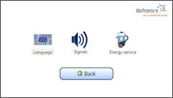
Figure 14: Settings menu
You can configure the following parameters in this menu:
- Language
- Signals
- Energy service (Power management)
Switch back to the home screen menu via the "Back" button.
7.6.1 Language SettingsSelect a language by tapping on the desired language. Use the arrow keys to scroll through the list. Confirm the selected language with the "OK" button (Figure 15). Switch back to the settings menu without saving changes by pressing the "Back" button instead of "OK".
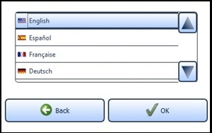
Figure 15: Language setting
7.6.2 Sound SettingsActivate and deactivate the audio signals for typing, warnings and sounds during the treatment. To do this, select the desired fields. A check mark means the sound is on.
Confirm with the "OK" button (Figure 16) to save your settings or close the menu via the "Back" button to discard the setting.
If "Turn off sound" is activated, all signal tones are switched off.
Important Note: Warning sounds will be emitted if an error occurs during operation of the lamp.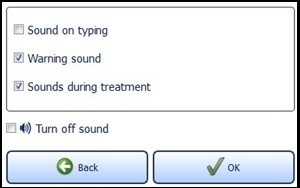
Figure 16: Sound setting
7.6.3 Energy Service (Power Management)
Providing the standby function is not manually deactivated via the check box "Never turn off lamp automatically" located near the bottom of the screen, the lamp will turn off after 10 minutes of non-use (Figure 17). You can change this time span in the menu "Energy service" via the plus and minus buttons. The settings are confirmed with the "OK" button and rejected with the "Back" button. In both cases you will return to the settings menu.
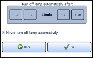
Figure 17: Energy management
If the configured time expires, a request appears for 10 seconds asking if you wish to prevent shut down. The LED lamp turns off automatically afterwards.
7.7 Service MenuAuthorization is required to access the service menu. Only authorized personnel can access the service menu.
8 Error MessagesThe BF-RhodoLED® has an integrated monitoring function. In the event of a malfunction, an error message will appear in the message display. Possible error messages are set out in the table below.
Error message Possible causes Measures Lamp overheated! - The temperature of the surrounding environment is too high.
- The ventilators or ventilator slots are blocked.
- The air inlets or outlets are adversely affected.
Wait until the standard temperature has been reached.
Check the ventilator and test the air inlets and outlets. Remove any visible foreign objects which may be present.
In case of continuing impairment of cooling please contact your local sales representative or Biofrontera.Lamp error!
Please inform your supplier.- Some of the LEDs have failed.
Further treatments may be carried out. However, please contact your local sales representative or Biofrontera immediately. Communication error! - Cable break in the touchscreen monitor spiral cord.
- Poor contact between the touchscreen monitor connection plug and the conduit box.
Confirm the communication error. Treatments can be continued in the treatment menu by pressing the "Start" button.
Please contact your local sales representative or Biofrontera.Lamp not calibrated! - The lamp is not calibrated.
- Improper calibration.
The lamp has to be calibrated. Please contact your local sales representative or Biofrontera immediately. Fehler-Nr.: 0084 Please inform your supplier. - A temperature sensor has failed.
The lamp head has to be repaired. Please contact your local sales representative or Biofrontera. Firmware of light head is faulty or missing!
Please inform your supplier.- An Update of the firmware has to be performed.
An update of the firmware has to be performed. Please contact your local sales representative or Biofrontera. If your LED lamp no longer functions properly for some unknown reason, proceed as follows:
- Unplug the power supply for half a minute and then plug back into the outlet (This action prompts a software reboot).
- Turn the lamp back on using the touchscreen monitor and verify functionality.
Should the problem persist, please contact your sales representative or Biofrontera. The lamp may not be used until the problem has been rectified.
For all other malfunctions and difficulties with operation please contact your sales representative or Biofrontera. You will find the contact details on page 2.
9 ServicingServicing may only be performed by Biofrontera-authorized personnel. If servicing is done by third parties, BF-RhodoLED® warranty is void and Biofrontera cannot be held responsible for potential malfunctions or damages of the device. It is recommended to have the lamp serviced after two years.
During service, the gas springs (gas pressure springs and gas traction springs) in the scissor arm as well as the general safety condition of the BF-RhodoLED® are checked.
Contact your sales representative or Biofrontera to schedule all service appointments.
10 Maintenance and CleaningThe device may under no circumstances be cleaned with aggressive cleaning agents or solvents (e.g. acetone or highly concentrated ethanol), as these promote wear and tear of the surface (paint coating), safety signs and graduated scale bar as well as the logo. Please avoid allowing any penetration of liquids into the lamp, BF-RhodoLED® is not waterproof and the electronics inside may be damaged.
Always unplug the lamp prior to cleaning and please observe the following cleaning practices:
Daily: Wipe the plexiglass screen located on the bottom of the lamp head with a damp soft cloth (e. g. a microfiber cloth). Weekly: Wipe the entire lamp. Do not use a very wet or dripping cleaning cloth. The unit is not waterproof, and damage could occur. Weekly cleaning can be carried out using a damp cloth. If a disinfection of the device is desired, a mild disinfecting agent can be used. Most commercially available products, which are suitable for plastics, should be compatible with BF-RhodoLED®. A know exception is the agent "Incidin PlusTM" (active ingredient: Glucoprotamine) which can cause corrosion of the lamp head surfaces.
Before using a disinfection agent, always refer to its manual to check for compatibility with plastic surfaces, especially with Plexiglas.
Note: If you notice any deterioration of a surface of BF-RhodoLED after using a disinfectant, please stop further use and contact Biofrontera.Please observe the following checks: Monthly: Check lamp for obvious visible damage such as damaged cables, worn off labeling, cracks on the lamp housing, etc. Do not use a damaged device for treatment and please inform your supplier. 11 Disposal Instructions
Follow all local and governmental disposal laws and regulations when disposing of the BF-RhodoLED®.
12 Technical Data12.1 Electrical connectors
Power supply unit:
- Primary wide-range input 100-240 VAC
- Secondary safety extra-low voltage output 48 VDC
- Secondary standby voltage output 5 VDC
Mother board for voltage management and control:
- Supply voltage input 48 VDC
- Standby voltage input 5 VDC plus Standby contact
- RS485 interface
- Output supply voltage HMI board 24 VDC
- 4 x ports LED board 8-pin (2 x LED circuits, temperature (3-pin))
- 4 x connector ventilator (2-pin)
LED board:
- 2 x ports mother board 8-pin (2 x LED circuits, temperature (3-pin))
Human Machine Interface (HMI) for operation:
- Supply voltage input 24 VDC
- RS485 interface
12.2 Specification
Type BF-RhodoLED®
Medical device class III; Device of protection class 1
Certification CSA certified Software Version No. 1.5_US_CAN Service life of the lamp Approx. 4 years Shelf life 1.5 years Number of LEDs 128 Typical peak wavelength 635 nm ± 5 nm Light dose (6 cm distance, 10 min) Approx. 37 J/ cm2 Typical irradiance 61 mW/cm2 +/- 15 % Max irradiance 77 mW/cm2 +/- 15 % (at 5 cm treatment distance) Illuminated area An area of 8x18 (approx. 3.1 x 7.1 inches) cm is illuminated. The effective treatment area is 6x16 cm (approx. 2.4 x 6.3 inches). Max. deviation of the intensity over the treatment area Approx. 15 % Transport and storage conditions Temperature: -30°C to +60°C (-22°F to +140°F)
Atmospheric pressure: 500 hPa - 1060 hPa
Relative humidity: 10% - 90%, non-condensingOperating conditions Temperature: 0°C to +40°C (32°F to +104°F)
Atmospheric pressure: 500 hPa - 1060 hPa
Operational altitude: ≤ 2000 m above NN
Relative humidity: 10% - 90%, non-condensing
This PDT lamp is suitable for continuous operation.Operating voltage 120-240 VAC, 50/60 Hz Output voltage 48 VDC Power consumption In calibrated normal operation: approx. 140 VA
In standby mode: approx. 85 VA
Over-voltage category II Degree of contamination 2 Material group (CTI) IIIb Protection class IP20 Size of the lamp 95 x 62 x 168 cm (37 x 24 x 66 inches)
Devices of batch 001 to 003: 127 x 56 x 168 cm (50 x 22 x 66 inches)Total lamp weight Approx. 52 kg (115 lbs)
Devices of batch 001 to 003: approx. 48 kg (106 lbs)For further information please directly contact Biofrontera.
13 Labeling and Symbols13.1 Labeling on the Lamp
The product sticker is located on the reverse side of the lamp base (see Figure 18). It contains manufacturer and product specifications (classification, serial and order number and the power supply used) as well as IP (Ingress) protection. In addition, a unique device identifier label is placed next to the product sticker.
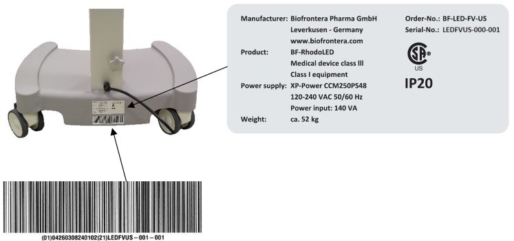
Figure 18: Product and UDI label. (The appearance of devices from batches 001 to 003 slightly differs. Appearance and location of the labels remain unaltered.)
Labels with safety instructions, special disposal instructions and further instructions are represented in the following figures.
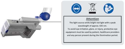
Figure 19: Instructions and notes on the lamp head
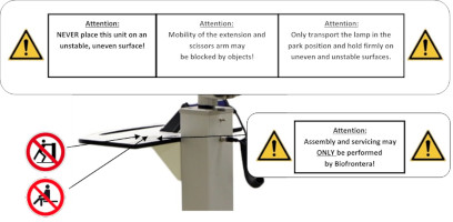
Figure 20: Instructions on the storage shelf. (The appearance of devices from batches 001 to 003 slightly differs. Appearance and location of the labels remain unaltered.)
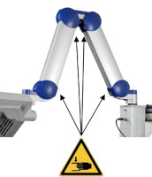
Figure 21: Instructions on the scissors arm. (The appearance of devices from batches 001 to 003 slightly differs. Appearance and location of the labels remain unaltered.)
Instructions for existing ground connector connections (see Figure 22) are located:
- Next to the grounding screws, which are located within and next to the power supply cover box beneath the mobile castor, respectively
- On the power supply cover box (see Figure 23)

Figure 22: Instructions for ground connector connection
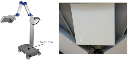
Figure 23: BF-RhodoLED®. (The appearance of devices from batches 001 to 003 slightly differs. Appearance and location of the labels remain unaltered.)
Instructions on the existing potential compensator conductor is located on the carrier bar beneath the potential compensator conductor (see Figure 24).
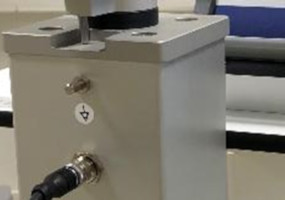
Figure 24: Potential compensator conductor. (The appearance of devices from batches 001 to 003 slightly differs. Appearance and location of the labels remain unaltered.)
All depicted symbols are summarized in a table in section 13.2 "Explanation of symbols".
13.2 Description of Symbols
Symbol Description 
Eye protection is required. IP20 IP (Ingress Protection):
Protection class of the housing against contact, foreign bodies and water
2 = against ingress of solid foreign bodies ≥ 12,5 mm Ø and larger
0 = Not protected against water
Technical and electric devices must not be disposed of with household waste. Please pay attention to the applicable disposal instructions found in the user manual. 
Symbol for existing ground connector connections 
Follow the instructions for use! 
General warning signs:
- Assembly and servicing may ONLY be performed by Biofrontera!
- Only transport lamp in the park position!
- The mobility of the extension and scissors arm may be obstructed by objects!
- Caution: heavy, do NOT lift alone.
- NEVER place this unit on an unstable, uneven surface!

Warning sign - risk of trapping fingers! 
Symbol for existing potential compensation conductor
Function/Application:
The purpose of a potential compensation conductor is to connect all conducting, metallic parts of a system to each other by the protective earthing in order to achieve the same electrical potential for the connected parts. Protection against contact voltage is thus guaranteed. Releasing the potential compensation conductor is forbidden. It should be firmly fitted to the support splint.
Please observe the requirements for ME-systems set out in EN 60601-1 when using the potential compensation cable (chapter 16).
Please do not stand on or push. There is a risk that the device may fall over through of the force applied. 
Please do not sit on the equipment. There is a risk that the device may fall over through the force applied.
13.3 Labeling on the Packaging- Attention: Protect from moisture and keep dry!
- Attention: Do not throw the package, damage possible!
- Attention: Please transport and store at -30°C/ -22°F to +60°C/ 140°F, a relative humidity of 10 % to 90 % and at an atmospheric pressure of 500 hPa (50 kPa) - 1060 hPa (106 kPa).

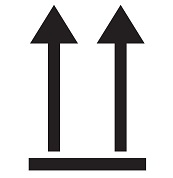
- This side up!
- Caution, one end of the package is heavy

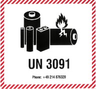
- Contains a lithium metal battery (optionally, not required starting from batch 007)
14 Electromagnetic compatibility (EMC)
BF-RhodoLED® meets the EMC requirements of the international standard EN60601-1-2:2015 Chapter 7 and 8. Other electrical devices can have an impact on the device. Using accessories that have not been approved can have a negative impact on the device and change the electromagnetic compatibility.
BF-RhodoLED® should not be used directly alongside or between other electrical devices.Guidelines and manufacturer's declaration - electromagnetic emissions BF-RhodoLED® is intended for operation in the electromagnetic environment detailed below.
The customer or operator of the device should ensure that it is operated in this environment.
Emission readings Conformity Electromagnetic environment - guidelines HF emissions CISPR 11 Group 1 BF-RhodoLED® only uses HF energy for its internal functionality.
For this reason, its HF emission is very low and it is not likely that neighbouring electronic devices would be disturbed.
HF emissions in accordance with CISPR 11
Harmonics in accordance with IEC 61000-3-2
Voltage fluctuations/flickers in accordance with IEC 61000 3-3
Class B
Class A
In compliance
BF-RhodoLED® is intended for operation in non-residential facilities and such like that are connected directly to a public low-voltage supply network that also supplies residential buildings. Guidelines and manufacturer's declaration - electromagnetic immunity BF-RhodoLED® is intended for operation in the electromagnetic environment detailed below.
The customer or operator of the device should ensure that it is operated in this environment.
Immunity tests IEC 60601 test levels Compliance level Electromagnetic environment - guidelines Static discharge in accordance with IEC 61000-4-2 ±8 kV contact discharge ±2 kV, ±4 kV, ±8 kV and ±15 kV air discharge ±8 kV contact discharge ±2 kV, ±4 kV, ±8 kV and ±15 kV air discharge Floors should be made of wood or concrete or finished with ceramic tiles. If the floor is finished with synthetic material, the relative air humidity must be at least 30 %. Fast, transient electrical disturbances/bursts in accordance with IEC 61000-4-4 ±2 kV for mains lines ±1 kV for input and output lines ±2 kV for mains lines The quality of the supply voltage should correspond to that of a typical commercial or hospital environment. Surges in accordance with IEC 61000-4-5 ±1 kV voltage outer conductor - outer conductor ±2 kV outer conductor - earth ±1 kV voltage outer conductor - outer conductor ±2 kV outer conductor - earth The quality of the supply voltage should correspond to that of a typical commercial or hospital environment. Voltage drops, brief interruptions and fluctuations in the supply voltage in accordance with IEC 61000-4-11 0 % UT for 0.5 cycles at phase angles of 0°, 45°, 90°, 135°, 180°, 225°, 270° and 315° (applicable only to me equipment connected to single-phase a.c. mains)
0 % UT for 1 cycle
70 % UT for 25/30 cycles
0 % UT for 250/300 cycles0 % UT for 0.5 cycles at phase angles of 0°, 45°, 90°, 135°, 180°, 225°, 270° and 315° (applicable only to me equipment connected to single-phase a.c. mains)
0 % UT for 1 cycle
70 % UT for 25/30 cycles
0 % UT for 250/300 cyclesThe quality of the supply voltage should correspond to that of a typical commercial or hospital environment.
If the operator of the device needs functionality to be maintained despite interruptions in the energy supply, it is advisable to run the device on an uninterruptable power supply or a battery.Power frequency (50/60 Hz) magnetic field in accordance with IEC 61000-4-8 3 A/m 3 A/m Mains frequency magnetic fields should correspond to the values typically found in the commercial and hospital
environment.
Comment: UT is the mains AC voltage prior to application of the test level
Guidelines and manufacturer's declaration - electromagnetic immunity BF-RhodoLED® is intended for operation in the electromagnetic environment detailed below. The customer or operator of the device should ensure that it is operated in this environment. Immunity tests IEC 60601 test levels Compliance level Electromagnetic environment - guidelines Conducted HF disturbances in accordance with IEC 61000-4-6
Radiated HF disturbances in accordance with IEC 61000-4-3
3 V
150 kHz to 80 MHz6 V
ISM bands 0.15 - 80 MHz
80 % AM with 1 kHz3 V/m 80 MHz to 2.7 GHz
80 % AM with 1 kHz3 V
6 V
3 V/m
Portable and mobile communication devices should not be used in closer proximity of the unit or its cables than the recommended safety distance of 300 mm.
Interference may occur in the vicinity of equipment marked with the following symbol.

Comment 1: These guidelines may not be applicable in all cases. The propagation of electromagnetic values is influenced by absorptions and reflections of buildings, objects, and people. Recommended safety distances between portable and mobile HF telecommunication devices and the BF-RhodoLED®
The BF-RhodoLED® is intended for use in the electromagnetic environment in which the HF disturbances are controlled.
The customer or operator of the device can help to avoid electromagnetic interference by maintaining the minimum safe distance between portable and mobile high-frequency telecommunication devices (transmitters) and the device. Portable RF communications equipment (radios, including their accessories such as antenna cables and external antennas) should not be used at a distance less than 30 cm (or 12 inches) from the manufacturer's specified parts and leads of the BF-RhodoLED®. Failure to do so may result in a reduction in the performance of the device.BF-RhodoLED® should not be used directly alongside or between other electrical equipment.
Guidelines and manufacturer's declaration - proximity fields from RF wireless communication equipment BF-RhodoLED® is intended for operation in the electromagnetic environment detailed below.
The customer or operator of the device should ensure that it is operated in this environment.
Service Frequency range/ discrete frequencies MHz Compliance level
[V/m]TETRA 400 390 27 GMRS 460, FRS 460 430 28 LTE Band 13, 17 734
746
7889 GSM 800/900, TETRA 800,
iDEN 820, CDMA,
LTE Band 5821
862
94828 GSM 1800, CDMA 1900,
GSM 1900,DECT,
LTE Band 1,3,4, 251730
1825
197028 Bluetooth, WLAN, 802.11 b/g/n, RFID 2450, LTE Band 7 2452 28 WLAN 802.11
a/n5240
5500
57009 Version 2.5
-
INSTRUCTION FOR USE

User Manual
Manufacturer: Biofrontera Pharma GmbH
Distributor: Biofrontera Inc.
ForewordThank you for choosing the RhodoLED® XL LED lamp for your photodynamic therapy. RhodoLED® XL has been developed in accordance with applicable technical standards to provide high energy efficiency as well as constant light emission at the desired wavelength.
Your lamp must be installed and maintained by a qualified Biofrontera technician and used only in accordance with the instructions in this manual. You may request the latest printed version covering this model from Biofrontera at any time.
Our drug Ameluz® and medical device RhodoLED® XL have been approved in combination for photodynamic therapy; the only approved use of our lamp is in combination with Ameluz® gel. This user manual provides important RhodoLED® XL product details, precautions and warnings, and operating instructions. For Ameluz®, please use its US prescribing information. The Ameluz® prescribing information includes information on how to use the gel along with contraindications, warnings and precautions and dosage and administration.Thorough reading and use of both this user manual and the Ameluz® USPI is required prior to treatment.
Our combination Ameluz®/RhodoLED® XL for photodynamic therapy is only to be used by physicians or healthcare professionals.For further questions about Ameluz®, RhodoLED® XL or the combination therapy please contact your sales representative or Biofrontera (Ameluz-US@biofrontera.com). See contact information below or visit us at http://www.biofrontera.us.com/
Sales representative:
Name:
Tel.:
E-mail:
Biofrontera Inc.
120 Presidential Way
Suite 330
Woburn, MA 01801
USA
Phone: (844) 426-3589Warranty and Disclaimers
Please see the terms and conditions of your contract for this information.Manufacturer
Biofrontera Pharma GmbH, Hemmelrather Weg 201, 51377 Leverkusen, Germany1 Intended Use
RhodoLED® XL is a red light-emitting LED lamp, which is used exclusively in combination with Ameluz® gel for lesion-directed and field-directed treatment of actinic keratoses of mild-to-moderate severity on the face and scalp.
2 RhodoLED® XL - General DescriptionRhodoLED® XL is comprised of three main components, the lamp head, an easily adjustable spring arm, and the mobile base with castors for smooth transport. In addition, the lamp has a convenient touchscreen monitor and aids for positioning the lamp head. The device is connected to the mains via a fixed mains supply cable.
3 Warnings and Precautions
The RhodoLED® XL has been developed for use in photodynamic therapy in combination with Ameluz® gel (excitation wavelength 635 nm). Any other use or combination of use is prohibited. 
During PDT side-effects such as application site erythema, pain, irritation, edema, pruritus, exfoliation, scab, induration and vesicles may occur. For further information please see Ameluz® USPI chapter 6. 
The user manual must be read carefully prior to using the RhodoLED® XL. 
The RhodoLED® XL may only be used by healthcare professionals who have received adequate training in its use. 
Bright light, do not stare into the light source 
Protective eye wear must be used by patient, healthcare providers and any persons present during the illumination period.
Do not stare in the LED beam. LEDs are classified in the exempt group according to IEC 62471:2006.

Distance sensor of RhodoLED® XL is a class 1 laser product in compliance with IEC 60825-1:2014. A class 1 laser product is safe under all conditions of normal use.

Risk of trapping fingers!
Depending on positioning, fingers can be trapped
between LED panels,
between LED panels and the holding bracket,
between the movable part and the fixed part of the lamp head holding bracket.
Neither the RhodoLED® XL nor the power supply unit should be exposed to excessive mechanical stress or serviced by unauthorized personnel. Assembly and servicing may only be carried out by Biofrontera qualified professionals. 
In order to avoid the risk of electrical shock, the device may only be connected to a power supply with a grounded connection. 
Neither the RhodoLED® XL nor its control unit may come into contact with water as this may lead to severe damage or electrical shock (exception: cleaning with a damp cloth). 
The RhodoLED® XL should be operated and housed indoors in areas with temperatures between 59 °F and 86 °F (15 °C and 30 °C), and relative humidity of 10 % to 90 %. 
Medical electronic devices require special precautionary measures with regard to the electro-magnetic compatibility (EMC); to avoid electro-magnetic disturbances, please do not place the device close to other electrical devices. 
There is a risk of tripping over the power cord or the lamp base. When transporting or when device is not in use, unplug and keep the power cord rolled up. 
Ensure that the control unit is always returned to parking position to avoid damage during transport. 
The control unit should not be exposed to strong external pressure or sharp objects. 
A person trained in operation of the RhodoLED® XL must always be present during treatment. 
Before treating affected skin area with the topical medication check the proper functioning of the RhodoLED® XL. Do not use a damaged device for treatment. 
RhodoLED® XL is intended for operation in non-residential facilities and such like that are connected directly to a public low-voltage supply network that also supplies residential buildings. RhodoLED® XL shall be operated in environments of professional health care facilities except in the vicinity of RF surgical equipment and outside the RF-shielded room of a magnetic resonance imaging system 
The RhodoLED® XL LED panels should only be used in curved shape and not in fully unfolded form. This is necessary to ensure the application of 37 J/cm² during the illumination. 
Do not place the device in such a way that it is difficult to disconnect the device's power plug from the mains during operation. 
The device must be protected against unauthorized use. Maintenance and initial set up of the RhodoLED® XL must be carried out by authorized personnel. In the event of servicing or set up being carried out by any other party, Biofrontera assumes no responsibility or liability regarding the safety or use of the device. 4 RhodoLED® XL Technical Description
4.1 Light emitting diodes (LED)
RhodoLED® XL is a red-light emitting LED lamp, comprised of three main components, the lamp head, an easily adjustable spring arm, and the mobile base with castors for smooth transport. In addition, the lamp has a convenient touchscreen monitor and aids for positioning the lamp head. RhodoLED® XL has 45 LEDs per panel with a total of 5 panels (225 LEDs), which emit a uniform, visible red light. The typical peak wavelength is approximately 635 nm with a half-band width of 16 nm.
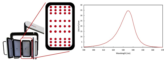
Figure 1: LED panels with LED distribution and emission spectrum of RhodoLED® XL LEDs.
The RhodoLED® XL LEDs are calibrated such that the skin being treated receives a light dose of approximately 37 J/cm2 under the following conditions:
- Illumination time of 13.5 minutes
- Treatment distance of 4.9 ± 0.6 inch (12.5 cm ± 1.5 cm)
The illumination area of the LED lamp is 9.06 x 11.42 inch (23 cm x 29 cm) for all panels in a curved shape.
The LEDs are distributed on each panel in a specific way (see Figure 1), such that they are more densely packed towards the upper and lower edges than in the center region of each panel. This distribution optimizes the homogeneity of illumination over the treated skin.
4.2 RhodoLED® XL ComponentsThe RhodoLED® XL consists of the following main components (Figure 2):
- Lamp head with telescope suspension
- Spring arm
- Control unit
- Mobile base (includes support rail, castors and power supply)
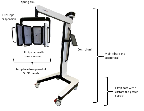
Figure 2: RhodoLED® XL main components
5 Operating environment of RhodoLED® XL
RhodoLED® XL shall be operated in environments of professional health care facilities. For a detailed description in electromagnetic compatibility see chapter 15. RhodoLED® XL is intended for operation in non-residential facilities and such like that are connected directly to a public low-voltage supply network that also supplies residential buildings.
6 Eye ProtectionProtective eye wear must be used by patient, healthcare providers and any persons present during the illumination period. Do not stare into the LED beam. RhodoLED® XL LEDs are classified in the exempt group product according to IEC 62471:2006. The operator and other persons present must wear protective glasses with a visible light transmission (VLT) of approximately 10 %. The patient must wear eye protection such as disposable eye protection pads or eye caps with an optical density for visible light of 6 or higher. Both options are effective and comfortable for use during treatment.
Note: Eyewear is not part of the medical device. Please carefully read any accompanying usage information before using any eye protection.
Protective eye wear must be used by patient, healthcare providers and any persons present during the illumination period.
Do not stare in the LED beam. LEDs are classified in the exempt group according to IEC 62471:2006.
7 RhodoLED® XL PDT Summarized Step-by-Step InstructionThese instructions should be used in conjunction with detailed operating instructions below (chapter 8). The section titles and numbers listed next to the instruction refer to the detailed instructions that correspond with each step.
Note: Every user of the RhodoLED® XL must be trained in operating the device. The initial training is provided by Biofrontera during set-up of the RhodoLED® XL. Recurrent training is not mandatory but can be provided by Biofrontera employees or other authorized parties. Before treating a patient with Ameluz®, please ensure that RhodoLED® XL is in good working order.STEP 1) Plug in the lamp. STEP 2) Turn on the lamp and wait for the home screen to appear (see chapter 8.4.3). STEP 3) Check the proper functioning of the RhodoLED® XL. STEP 4) Treat the affected skin area: Application, incubation, and removal of the topical medication according to the USPI of Ameluz®. STEP 5) Position the patient comfortably and equip the patient with protective eyewear (see chapter 6). STEP 6) Select active panels (see chapter 8.4.5). STEP 7) Position the lamp and adjust the lamp head over the skin area to be treated (distance 4.9 inch /12.5 cm) (see chapter 8.4.6). STEP 8) Put on protective eyewear and make sure anyone remaining in the treatment room also wears protective eyewear (see chapter 6). STEP 9) Start treatment by pressing Start, the illumination period begins (see chapter 8.4.9).
Remind the patient to remain still throughout the illumination period.
If audible indicators during treatment are activated, explain the sounds to the patient.
If the patient needs a break, press Pause on the screen.
To resume treatment, press Resume (see chapter 8.4.10).
To abort the illumination, press Cancel (see chapter 8.4.10).
Always stay with the patient during the illumination period.STEP 10) At the end of the illumination period, remove patient's protective eyewear and follow further instructions in the Ameluz® USPI.
8 Detailed Operating InstructionsNote: Every user of the RhodoLED® XL must be trained in operating the device. The initial training is provided by Biofrontera during set-up of the RhodoLED® XL. Recurrent training is not mandatory but can be provided by Biofrontera employees. The device must be protected against unauthorized use.

Protective eye wear must be used by patient, healthcare providers and any persons present during the illumination period.
Do not stare in the LED beam. LEDs are classified in the exempt group according to IEC 62471:2006.
8.1 Transport of RhodoLED® XL and Spring Arm Lock FunctionDuring transportation the RhodoLED® XL must be in the transport position (see Figure 3). For the transport position the spring arm is moved down as far as possible and the locking bolt at the joint between head and spring is moved to the right (Figure 3). In this position, the spring arm is locked and cannot be moved upwards. To release the spring arm lock, push the locking bolt to the left (Figure 3). The locking function is located at the bottom of the spring arm, close to the lamp head connection.
For transport, please ensure that the control unit of RhodoLED® XL is placed on the left side (see Figure 3).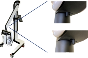
Figure 3: Transport position of RhodoLED® XL and locking function of spring arm. Locking function is located at the bottom of the spring arm, close to the lamp head connection.
8.2 Movement Areas
The swivel range of the spring arm to the left and right of the main axis is +/- 5°. The vertical range of the spring arm is 68°. The spring arm with internal gas spring allows seamless adjustment to any height. The lamp head can be rotated by 360° (Figure 4). In addition, the panels can be tilted up to 90 ° at the holding bracket (Figure 4).
Note: If the spring arm is at the top, it may collide with the LED panels when they are rotated 360°.
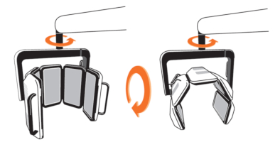
Figure 4: Rotation and tilting of the lamp head.
The orientation of the panels can be changed from a curved shape to an unfolded form by pulling the holding bracket apart (Figure 5).
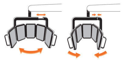
Figure 5: Movement range of the lamp head.
Note: The RhodoLED® XL LED panels should only be used in curved shape and not in a fully unfolded form. This is necessary to ensure the application of 37 J/cm² during the illumination.
The control unit can be turned from the left to the right side of the device (see Figure 6). The control unit must be brought completely into the selected position until it snaps into place.
Note: If the control unit is not snapped into position, there may be a collision between the spring arm and the control unit.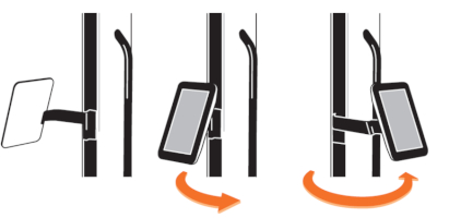
Figure 6: Control unit positions
8.3 Turning RhodoLED® XL On and Off
Note: Before turning on the lamp, the power cord must be plugged in into the power grid. RhodoLED® XL is intended for operation in non-residential facilities and such like that are connected directly to a public low-voltage supply network that also supplies residential buildings.
Note: Do not place the device in such a way that it is difficult to disconnect the device's power plug from the mains during operation.
The RhodoLED® XL is equipped with a cable winding system. To unwind the cable, pull the plug out of the opening of the lamp base. When the cable is being unwound, a clicking sound is heard. The power button is located on the right side of the control unit. With the lamp plugged in, press the power button to start the device.
To power down the device, press the power button and the device shuts down. RhodoLED® XL can also be switched off via the software. To switch the device off, press the software power button in the upper right corner. To rewind the cable, remove the plug from the wall socket and slightly pull on the cable once. Hold the cable loosely in your hand to allow rewinding. The cable winder will pull the cable in automatically until it is fully rolled up. Do not completely release the cable when winding it up to avoid damage of the device.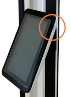
Figure 7: Control unit of RhodoLED® XL with power button
8.4 RhodoLED® XL Controls8.4.1 Control Unit
The touchscreen of the control unit can be used while wearing commercially available examination gloves.
8.4.2 Splash Screen
The Biofrontera corporate logo and software version are displayed during the LED lamp operating system start-up (Figure 8). The operating system takes approximately 10 seconds to load.

Figure 8: Splash screen
8.4.3 Home ScreenThe home screen appears after the operating system has loaded.
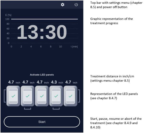
Figure 9: Home screen
8.4.4 The Treatment Profile
The RhodoLED® XL has a fixed LED light intensity which ensures the application of 37 J/cm² within the 13.5-minute treatment time.
8.4.5 Selecting Active LED Panels
The device has 5 LED panels which are also displayed by the software (Figure 10). The illustrated panels are visible from the back side and the corresponding panel of the device can be identified via the handles, starting from the left. All panels are activated by default and can be deactivated via the software. To deactivate LED panels, press on the illustrated panel. For easier orientation, the panel number can also be found at the backside of the respective panel (Figure 11).

Figure 10: Software illustration of RhodoLED® XL LED panels (all panels are activated)
Figure 11: Panel number at the backside of the panel
Deactivated panels are displayed in grey with a power symbol in their centers (Figure 12). Activated panels are highlighted and the current distance to the treatment area is displayed.
Figure 12: Coloring of a switched off panel
8.4.6 Treatment AreaThe illumination area of RhodoLED® XL is 9.06 x 11.42 inch (23 cm x 29 cm) when all panels are arranged in the standard curved shape. This usually allows a full-face illumination. However, face and head sizes are subject to strong variations between patients. As a rough guidance, the midlines of the outer two panels marks the outer boundaries of the illumination area (see Figure 13 as guidance).
Note: The RhodoLED® XL LED panels should only be used in curved shape and not in fully unfolded form. This is necessary to ensure the application of 37 J/cm² during the illumination.
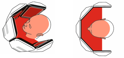
Figure 13: Treatment area of RhodoLED® XL from the side and in top view.
Note: If less than 5 panels are used for a treatment, it must be ensured that at least three adjacent panels are used. The treatment area is thereby reduced and reaches from the midline of the one outer panel to the other midline of the other outer panel.
If a treatment with less than 5 active LED panels is started, a message dialog appears which must be confirmed.8.4.7 Adjusting the Treatment Distance
The correct treatment distance for the RhodoLED® XL is 4.9 ± 0.6 inch (12.5 ± 1.5 cm). Each LED panel is equipped with a distance sensor to allow individual adjustment of all panels. The distance sensor is automatically switched on if the panel is switched on. The current distance of each panel is shown on the control unit display above the panel illustration. The following table summarizes the visualization of the treatment distance.
Note: When starting the treatment, the LED panels that are too close or too far away from the treatment area will nevertheless also light up. To disable an LED panel during the treatment it must be switched off on the display (see Figure 12).
Table 1: Adjusting the treatment distance
Pictogram Meaning 
Treatment distance is correct for this LED panel (4.9 ± 0.6 inch / 12.5 ± 1.5 cm), adjustment light is/turns on 
Treatment distance is too small for this LED panel. LED panel must be further away from treatment area, adjustment light is/turns off 
Treatment distance is too large for this LED panel. LED panel must be closer to the treatment area, adjustment light is/turns off 
This LED panel is switched off 8.4.8 Adjustment Light
If the correct treatment distance of 4.9 inch (12.5 cm) is set the LEDs of the panel light up at a low light intensity to allow an easy adjustment of the distance and the target treatment area.
The size of the treatment area is 9.06 x 11.42 inch (23 cm x 29 cm) for all panels in a curved shape.
Note: When starting the treatment, the LED panels that are too close or too far away from the treatment area will nevertheless also light up. To disable an LED panel during the treatment it must be switched off on the display (see Figure 12).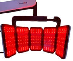
Figure 14: Low light intensity for correct adjustment of LED panels.
8.4.9 Starting an Illumination
To start a treatment, press the Start button. Before starting the treatment make sure every person present wears the correct eye protection (see chapter 6) and confirm the query for eye protection (Figure 15).

Protective eye wear must be used by patient, healthcare providers and any persons present during the illumination period.
Do not stare in the LED beam. LEDs are classified in the exempt group according to IEC 62471:2006.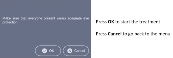
Figure 15: Note on eye protection before starting treatment.
During the illumination, the remaining treatment time is displayed in the diagram. The progress is marked green in the profile and with a green dotted vertical line (Figure 16).
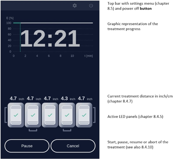
Figure 16: Treatment progress.
8.4.10 Pause, continue, or cancel a treatment
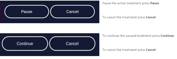
Figure 17: Pause, continue, and cancel a treatment.
To abort the current treatment, press the Cancel button. The applied light dose and the remaining treatment time is displayed in a query. Confirm the query to cancel the treatment (Figure 18).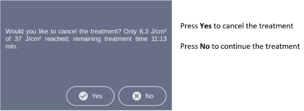
Figure 18: Cancelled treatment message shows applied light dose and remaining treatment time.
Note: If you cancel prior to the end of the total treatment time, the internal timer will reset. The remaining treatment time will not be saved.
After pressing Cancel and Yes or upon completion of the treatment the software will automatically return to the home screen.
8.4.11 Audio Signals During Treatment
After completion of the first half of the treatment the patient will hear an audio signal, indicating the treatment progress. A second signal indicates treatment completion, and the lamp will stop the illumination. Audio signals can be deactivated via the settings menu (see chapter 8.5.4).
Further audio signals occur for queries that must be confirmed and may occur in the event of an error. A description of possible errors can be found in chapter 9.
8.5 Settings Menu
To open the settings menu, select the gear symbol in the upper right corner of the screen. The settings menu is organized in the tabs General, Service and Info.
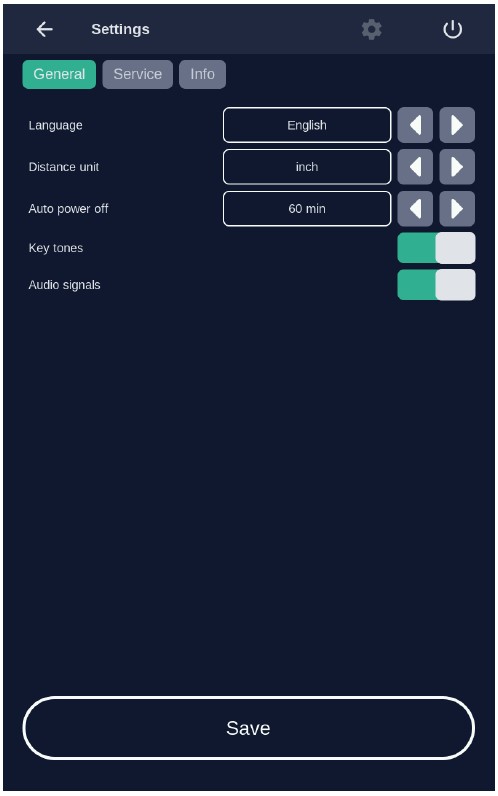
Figure 19: The settings menu is organized in the three main tabs General, Service and Info
8.5.1 LanguageLanguage settings are part of the General settings tab. Select a language by tapping on the left and right arrows. The software provides the languages English, Spanish and German.
Confirm the selected language by pressing the Save button, to discard the settings leave the menu without pressing Save.
8.5.2 Distance UnitsUnit settings are part of the General settings tab. The distance of the LED panels to the treatment area can be displayed in inch or in cm. Select a distance unit by tapping on the arrows.
Confirm the selected distance unit by pressing the Save button, to discard the settings leave the menu without pressing Save.8.5.3 Auto power off
Auto power off settings are part of the General settings tab. The auto power off setting is used to set the time after which the lamp is automatically switched off. Values of 15, 30, 60 and 120 minutes can be selected.
Confirm your selected auto power off time by pressing Save, to discard the settings leave the menu without pressing Save.8.5.4 Sound Settings
Sound settings are part of the General settings tab. Activate and deactivate the audio signals for typing and sounds during the treatment. To do this, activate or deactivate the corresponding sliding switch. A green slider means the sound is currently switched on.
Confirm your selection by pressing Save, to discard the settings leave the menu without pressing Save.
Note: Warning sounds will be emitted if an error occurs during operation of the lamp. Warning sounds cannot be turned off.
8.5.5 Info-TabThe system status provides information about the current hardware and software status of the device.
This includes information about:
• The serial numbers of the systems core components
• Unique device identifier (UDI, see chapter 14.1)
• Automatic switch off settings
• Software version
• List of occurred errors (chapter 9)
Note: In case of a malfunction of the device, please have this information available.
8.5.6 Service Menu
Authorization is required to access the service menu. Only authorized personnel can access the service menu. See also chapter 10.
9 Error MessagesThe RhodoLED® XL has an integrated monitoring function. In the event of a malfunction, an error message will appear in the message display. Possible error messages are set out in the table below. Please ensure that you always correctly record the error code when contacting Biofrontera customer service in case of an error message.
Note: even if usage of the lamp is still possible in case of an error, please contact your local sales representative or Biofrontera if an error message persists.
Error code Possible causes Measures 001 System error Error in system of the device - Confirm the system error
- Please contact your local sales representative or Biofrontera002 Communication error Communication between the control unit and the LED panels disturbed - Confirm the communication error
- Treatment can be continued by confirming the message dialog
- Please contact your local sales representative or Biofrontera
- If there is a permanent error in the communication, no further treatment is possible003 Panel error

Error in the control of one or more LED panel
Defective LED panels are marked with a red triangle- Confirm the Panel error
- Treatment can be continued by confirming the message dialog
- Please contact your local sales representative or Biofrontera004 Distance sensor error Error in control of the distance sensors - Confirm the Distance sensor error
- Treatment can be continued by confirming the message dialog
- Please contact your local sales representative or Biofrontera005 Update process error The software needs updating - Please contact your local sales representative or Biofrontera 006 Temperature sensor error Defective temperature sensor of defect in temperature sensor control - Confirm the Distance sensor error
- Treatment can be continued by confirming the message dialog
- Please contact your local sales representative or Biofrontera007 Cooling system warning The temperature of the surrounding environment is too high
The ventilators or ventilator slots are blocked
The air inlets or outlets are adversely affected- Wait until the standard temperature has been reached
- Check the ventilators and test the air inlets and outlets- Remove any visible foreign objects which may be present
- In case of continuing impairment of the cooling system, please contact your local sales representative or BiofronteraIf your RhodoLED® XL no longer functions properly for some unknown reason, proceed as follows:
- Unplug the power supply for half a minute and then plug back into the outlet (This action prompts a software reboot).
- Turn the lamp back on using the control unit and verify functionality.
Should the problem persist, please contact your sales representative or Biofrontera. The lamp may not be used until the problem has been rectified.
For all other malfunctions and difficulties with operation please contact your sales representative or Biofrontera. You will find the contact details on page 2 of the manual.
Please have the system status (chapter 8.5.5) available if you contact your sales representative or Biofrontera.
10 Servicing and repairsServicing and repairs may only be performed by Biofrontera-authorized personnel. For RhodoLED® XL no spare parts for replacement by the user are available.
Device is not serviced while in use with patients.
If servicing or repairs are done by third parties, RhodoLED® XL warranty is void and Biofrontera cannot be held responsible for potential malfunctions of or damages to the device or the patients.
Figure 20: Servicing and maintenance may only be performed by Biofrontera
11 Maintenance and CleaningThe device may under no circumstances be cleaned with aggressive cleaning agents or solvents (e.g. acetone or highly concentrated ethanol), as these promote wear and tear of the surface (paint coating) and labeling. Please use only a damp cloth when wiping over the labels.
Please avoid allowing any penetration of liquids into the lamp, RhodoLED® XL is not waterproof and the electronics inside may be damaged. Do not maintain or clean the device while in use with patients.
Always unplug the lamp prior to cleaning and please observe the following cleaning practices:
Daily: Wipe the plexiglass screen located on the bottom of the lamp head with a damp soft cloth (e. g. a microfiber cloth). Weekly: Wipe the entire lamp. Do not use a very wet or dripping cleaning cloth. The unit is not waterproof and damage could occur. Weekly cleaning can be carried out using a damp cloth or Multi-Purpose Cleaners (Clorox Healthcare VersaSure Wipes). Please observe the following checks: Monthly: Check lamp for obvious visible damage such as damaged cables, worn off labeling, cracks on the lamp housing, etc. Do not use a damaged device for treatment and please inform your supplier.
12 Disposal Instructions
Follow all local and governmental disposal laws and regulations when disposing of the RhodoLED® XL.
13 Technical Data13.1 Electrical Connectors
Power supply unit:
- Primary wide-range input 100-120 VAC
- Secondary safety extra-low voltage output 48 VDC
- Secondary standby voltage output 5 VDC
LED controller board:
- Supply voltage input 48 VDC
- 2x CAN interface (2 pin)
- LED board FFC (12 pin)
- Distance sensor FFC (4 pin)
- 2 x connector ventilator (3 pin)
LED board:
- LED controller board FFC 12 pin (3 x LED circuits, temperature)
- Distance sensor FFC (4 pin)
Human Machine Interface (HMI) for operation:
- Supply voltage input 48 VDC (2 pin)
- Secondary standby voltage input 5 VDC (4 pin)
- CAN interface (3 pin)
- USB interface (5 pin, covered)
- Speaker (2 pin)
- Touch controller (4 pin)
- Display backlight (6 pin)
- Display data LVDS (20 pin)
- On/off switch (2 pin)
- MHI module to pillar external connector (9 pin)
13.2 Specification
Type RhodoLED® XL
Medical device class III; Device of protection class 1
Certification UL certified E513735 Software Version No. g2.12.00.3739 Service interval Biofrontera recommends performing service every 2 years Number of LEDs 225 Typical peak wavelength 635 nm ± 5 nm Light dose Approx. 37 J/ cm2 at 4.9 inch (12.5 cm) distance, 13.5 min
Typical irradiance approx. 46 mW/cm² ± 20 % at 4.9 inch (12.5 cm) distance Max irradiance approx. 55 mW/cm² at 4.9 inch (12.5 cm) distance Illuminated area An area of 9.06 x 11.42 inch (23 cm x 29 cm) is illuminated using all panels in curved shape. Max. deviation of the intensity over the treatment area Approx. 20 % Treatment distance 4.9 ± 0.6 inch (12.5 cm ± 1.5 cm)
Measuring accuracy ± 0.3 cm (0.1 inch)Transport conditions Temperature: -4 °F to +140 °F (-20 °C to +60 °C)
Atmospheric pressure: 500 hPa - 1060 hPa
Relative humidity: 10 % - 90 %, non-condensingStorage conditions Temperature: +59 °F to +95 °F (+ 15 °C to +35 °C)
Atmospheric pressure: 500 hPa - 1060 hPa
Relative humidity: 10 % - 90 %, non-condensing
Maximum storage time 180 daysOperating conditions Temperature: +59 °F to +86 °F (+15 °C to + 30 °C)
Atmospheric pressure: 500 hPa - 1060 hPa
Operational altitude: ≤ 4800 m above NN
Relative humidity: 10 % - 90 %, non-condensing.
RhodoLED® XL must be operated in environments of professional healthcare facilities.Operating voltage 100-120 VAC, 60 Hz Output voltage 48 VDC Power consumption In normal operation: approx. 750 VA
In standby mode: approx. 85 VAOver-voltage category II Degree of contamination 2 Material group (CTI) IIIb Protection class IP20 Size of the lamp Height 5.76 ft (175.5 cm)
Width: 2.51 ft (76.4 cm)
Depth: 3.19 ft (97.1 cm)Total lamp weight 165 lb. (75 kg) For further information please directly contact Biofrontera.
14 Labeling and Symbols14.1 Label on the Lamp Base
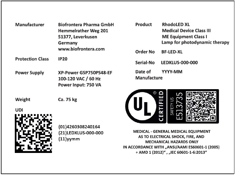
Figure 21: Product label (serial number and date of manufacturing vary) with UDI code of RhodoLED® XL on lamp base, individual code depends on the serial number and date of manufacturing of the device.
Figure 22: No stepping on the device, no disposal in household waste, information on setup and service.

Figure 23: Instruction for ground connector connection (not visible from the outside)
14.2 Label on LED Panels
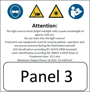
Figure 24: Instruction and notes on the LED panels
Figure 25: LED Panel numbering from Panel 1 to Panel 5
14.3 Description of Symbols
Symbol Description 
Eye protection is required. 

Distance sensor of RhodoLED® XL is a class 1 laser product. A class 1 laser product is safe under all conditions of normal use. IP20 IP (Ingress Protection):
Protection class of the housing against contact, foreign bodies and water
2 = against ingress of solid foreign bodies ≥ 12,5 mm Ø and larger
0 = Not protected against water
Technical and electric devices must not be disposed of with household waste. Please pay attention to the applicable disposal instructions found in the user manual. 
Symbol for existing ground connector connections 
Follow the instructions for use! 
General warning signs:
- Assembly and servicing may ONLY be performed by Biofrontera
- Only transport lamp in the park position
- Caution: heavy, do NOT lift alone.

Warning sign - risk of trapping fingers! 
Bright light, do not stare into the light source 
Do not step on the device.
15 Electromagnetic compatibilityRhodoLED® XL complies with the EMC requirements of IEC 60601-1-2:2014 + A1:2020. Other electrical devices can influence the device.
The use of accessories, transducers and cables other than those specified or provided by the manufacturer may result in increased electromagnetic emissions or reduced electromagnetic immunity of the equipment and may lead to incorrect operation. Assembly, service and repairs may only be performed by Biofrontera.
Guidelines and manufacturer's declaration - electromagnetic emissions RhodoLED® XL is intended for operation in the electromagnetic environment detailed below.
The customer or operator of the device should ensure that it is operated in this environment.
The emission characteristics of RhodoLED® XL allow its use in industrial and hospital and healthcare professional environments (CISPR 11, Class A). When used in a residential environment (for which CISPR 11 normally requires Class B), this device may not provide adequate protection of radio services. The user may need to take corrective action by moving or repositioning the device.Emission readings Conformity Electromagnetic environment - guidelines HF emissions CISPR 11 Group 1 RhodoLED® XL only uses HF energy for its internal functionality. For this reason, its HF emission is very low and it is not likely that neighboring electronic devices would be disturbed. HF emissions in accordance with CISPR 11 Class A RhodoLED® XL is intended for operation in non-residential facilities and such like that are connected directly to a public low-voltage supply network that also supplies residential buildings. Harmonics in accordance with IEC 61000-3-2 Class A Voltage fluctuations/flickers in accordance with IEC 61000-3-3 In compliance Guidelines and manufacturer's declaration - electromagnetic immunity RhodoLED® XL is intended for operation in the electromagnetic environment detailed below. The customer or operator of the device should ensure that it is operated in this environment. Immunity tests IEC 60601 test levels Compliance level Electromagnetic environment - guidelines Static discharge in accordance with IEC 61000-4-2 ±8 kV contact discharge ±2 kV, ±4 kV, ±8 kV and ±15 kV air discharge
±8 kV contact discharge ±2 kV, ±4 kV, ±8 kV and ±15 kV air discharge Floors should be made of wood or concrete or finished with ceramic tiles. If the floor is finished with synthetic material, the relative air humidity must be at least 30 %. Fast, transient electrical disturbances/bursts in accordance with IEC 61000-4-4 ±2 kV for mains lines 100 kHz repetition frequency ±2 kV for mains lines The quality of the supply voltage should correspond to that of a typical commercial or hospital environment. Surges in accordance with IEC 61000-4-5 ±1 kV voltage outer conductor - outer conductor ±2 kV outer conductor - earth ±1 kV voltage outer conductor - outer conductor ±2 kV outer conductor - earth The quality of the supply voltage should correspond to that of a typical commercial or hospital environment. Voltage dips, brief interruptions and fluctuations in the supply voltage in accordance with IEC 61000-4-11 0 % UT for 0.5 cycles at phase angles of 0°, 45°, 90°, 135°, 180°, 225°, 270° and 315° (applicable only to me equipment connected to single-phase a.c. mains)
0 % UT for 1 cycle
70 % UT for 25/30 cycles
0 % UT for 250/300 cycles0 % UT for 0.5 cycles at phase angles of 0°, 45°, 90°, 135°, 180°, 225°, 270° and 315° (applicable only to me equipment connected to single-phase a.c. mains)
0 % UT for 1 cycle
70 % UT for 25/30 cycles
0 % UT for 250/300 cyclesThe quality of the supply voltage should correspond to that of a typical commercial or hospital environment.
If the operator of the device needs functionality to be maintained despite interruptions in the energy supply, it is advisable to run the device on an uninterruptable power supply or a battery.Power frequency (50/60 Hz) magnetic field in accordance with IEC 61000-4-8 30 A/m 30 A/m Mains frequency magnetic fields should correspond to the values typically found in the commercial and hospital environment. Comment: UT is the mains AC voltage prior to application of the test level Guidelines and manufacturer's declaration - electromagnetic immunity RhodoLED® XL is intended for operation in the electromagnetic environment detailed below. The customer or operator of the device should ensure that it is operated in this environment. Immunity tests IEC 60601 test levels Compliance level Electromagnetic environment - guidelines Conducted HF disturbances
in accordance
with IEC 61000-4-6
3 V
150 kHz to 80 MHz
6 V
ISM bands 0.15 - 80 MHz
80 % AM with 1 kHz3 V
6 V
Portable and mobile communication devices should not be used in closer proximity of the unit or its cables than the recommended safety distance of 300 mm.
Radiated HF disturbances
in accordance
with IEC 61000-4-3
3 V/m 80 MHz to 2.7 GHz
80 % AM with 1 kHz3 V/m Interference may occur in the vicinity of equipment marked with the following symbol.

Comment 1: These guidelines may not be applicable in all cases. The propagation of electromagnetic values is influenced by absorptions and reflections of buildings, objects, and people. Recommended safety distances between portable and mobile HF telecommunication devices and the RhodoLED® XL. Portable RF communications equipment (radios, including their accessories such as antenna cables and external antennas) should not be used at a distance less than 30 cm (or 12 inch) from the manufacturer's specified parts and leads of the RhodoLED® XL. Failure to do so may result in a reduction in the performance of the device.
RhodoLED® XL should not be used directly alongside or between other electrical equipment.Guidelines and manufacturer’s declaration – proximity fields from RF wireless communication equipment RhodoLED® XL is intended for operation in the electromagnetic environment detailed below. The customer or operator of the device should ensure that it is operated in this environment. Service Frequency range/ discrete frequencies MHz Compliance level
[V/m]TETRA 400 385 27 GMRS 460, FRS 460 450 29 LTE Band 13, 17 710
745
7809 GSM 800/900, TETRA 800,
iDEN 820, CDMA,
LTE Band 5810
870
93028 GSM 1800, CDMA 1900,
GSM 1900,DECT,
LTE Band 1,3,4, 251720
1845
197028 Bluetooth, WLAN, 802.11 b/g/n, RFID 2450, LTE Bamd 7 2450 28 WLAN 802.11
a/n5240
5500
57859 Version 1.6 SW_G2
-
PRINCIPAL DISPLAY PANEL – OUTER PACKAGING
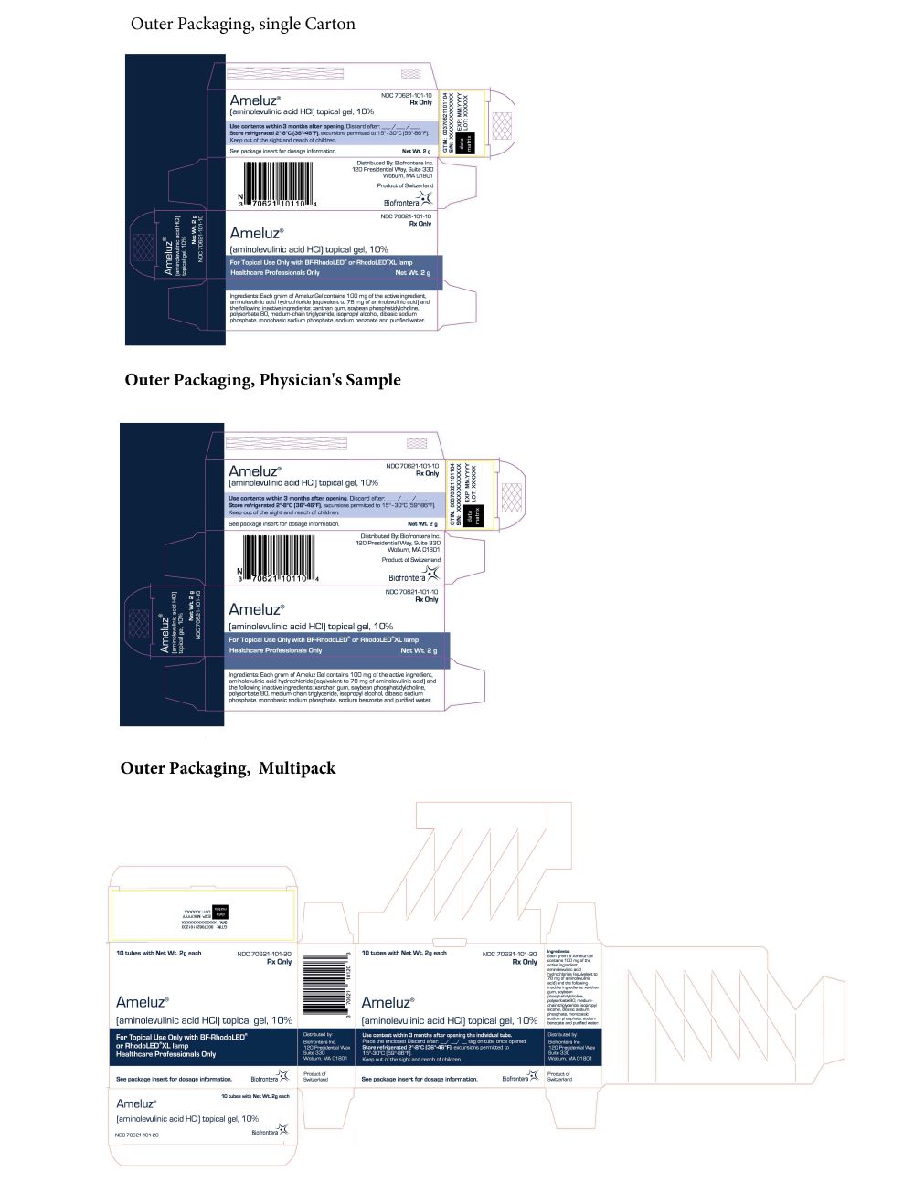
Outer Packaging, single Carton
NDC 70621-101-10
Ameluz® Rx Only
(aminolevulinic acid HCl) topical gel, 10%
Use contents within 3 months after opening. Discard after: __/ __/ __.
Store refrigerated 2°-8°C (36°-46°F), excursions permitted to 15°-30°C (59°-86°F).
Keep out of the sight and reach of children.
See package insert for dosage information. Net Wt. 2 g
Distributed By: Biofrontera Inc.
120 Presidential Way, Suite 330
Woburn, MA 01801
Product of Switzerland
For Topical Use Only with BF-RhodoLED® or RhodoLED® XL lamp
Healthcare Professionals Only
Ingredients: Each gram of Ameluz Gel contains 100 mg of the active ingredient, aminolevulinic acid hydrochloride (equivalent to 78 mg of aminolevulinic acid) and the following inactive ingredients: xanthan gum, soybean phosphatidylcholine, polysorbate 80, medium-chain triglyceride, isopropyl alcohol, dibasic sodium phosphate, monobasic sodium phosphate, sodium benzoate and purified water
Outer Packaging, Physician's Sample
NDC 70621-101-30
Ameluz® Rx Only
Physician's Sample
Not for sale
(aminolevulinic acid HCl) topical gel, 10%
Use contents within 3 months after opening. Discard after: __/ __/ __.
Store refrigerated 2°-8°C (36°-46°F), excursions permitted to 15°-30°C (59°-86°F).
Keep out of the sight and reach of children.
See package insert for dosage information. Net Wt. 2 g
Distributed By: Biofrontera Inc.
120 Presidential Way, Suite 330
Woburn, MA 01801
Product of Switzerland
For Topical Use Only with BF-RhodoLED® lamp or RhodoLED® XL lamp
Healthcare Professionals Only
Ingredients: Each gram of Ameluz Gel contains 100 mg of the active ingredient, aminolevulinic acid hydrochloride (equivalent to 78 mg of aminolevulinic acid) and the following inactive ingredients: xanthan gum, soybean phosphatidylcholine, polysorbate 80, medium-chain triglyceride, isopropyl alcohol, dibasic sodium phosphate, monobasic sodium phosphate, sodium benzoate and purified water
Outer Packaging, Multipack10 tubes with Net Wt. 2g each NDC 70621-101-20
Ameluz® Rx Only
(aminolevulinic acid HCl) topical gel, 10%
For Topical Use Only with BF-RhodoLED® lamp or RhodoLED® XL lamp
Healthcare Professionals Only
See package insert for dosage information.
Distributed By: Biofrontera Inc.
120 Presidential Way, Suite 330
Woburn, MA 01801
Product of Switzerland
10 tubes with Net Wt. 2g each NDC 70621-101-20
Ameluz® Rx Only
(aminolevulinic acid HCl) topical gel, 10%
Use contents within 3 months after opening the individual tube.
Place the enclosed Discard after: __/ __/ __.tag on tube once opened.
Store refrigerated 2°-8°C (36°-46°F), excursions permitted to 15°-30°C (59°-86°F).
Keep out of the sight and reach of children.
See package insert for dosage information.
Ingredients:
Each gram of Ameluz Gel contains 100 mg of the active ingredient, aminolevulinic acid hydrochloride (equivalent to 78 mg of aminolevulinic acid) and the following inactive ingredients: xanthan gum, soybean phosphatidylcholine, polysorbate 80, medium-chain triglyceride, isopropyl alcohol, dibasic sodium phosphate, monobasic sodium phosphate, sodium benzoate and purified waterDistributed By: Biofrontera Inc.
120 Presidential Way, Suite 330
Woburn, MA 01801
Product of Switzerland
-
INGREDIENTS AND APPEARANCE
AMELUZ
aminolevulinic acid hydrochloride gelProduct Information Product Type HUMAN PRESCRIPTION DRUG Item Code (Source) NDC:70621-101 Route of Administration TOPICAL Active Ingredient/Active Moiety Ingredient Name Basis of Strength Strength AMINOLEVULINIC ACID HYDROCHLORIDE (UNII: V35KBM8JGR) (AMINOLEVULINIC ACID - UNII:88755TAZ87) AMINOLEVULINIC ACID HYDROCHLORIDE 100 mg in 1 g Inactive Ingredients Ingredient Name Strength XANTHAN GUM (UNII: TTV12P4NEE) LECITHIN, SOYBEAN (UNII: 1DI56QDM62) POLYSORBATE 80 (UNII: 6OZP39ZG8H) MEDIUM-CHAIN TRIGLYCERIDES (UNII: C9H2L21V7U) ISOPROPYL ALCOHOL (UNII: ND2M416302) SODIUM PHOSPHATE, DIBASIC, DIHYDRATE (UNII: 94255I6E2T) SODIUM PHOSPHATE, MONOBASIC, DIHYDRATE (UNII: 5QWK665956) SODIUM BENZOATE (UNII: OJ245FE5EU) WATER (UNII: 059QF0KO0R) Packaging # Item Code Package Description Marketing Start Date Marketing End Date 1 NDC:70621-101-10 1 in 1 PACKAGE 06/01/2017 1 NDC:70621-101-01 2 g in 1 TUBE; Type 7: Separate Products Requiring Cross Labeling 2 NDC:70621-101-30 1 in 1 PACKAGE 06/01/2017 2 NDC:70621-101-03 2 g in 1 TUBE; Type 7: Separate Products Requiring Cross Labeling 3 NDC:70621-101-20 10 in 1 PACKAGE 05/10/2021 3 NDC:70621-101-01 2 g in 1 TUBE; Type 7: Separate Products Requiring Cross Labeling Marketing Information Marketing Category Application Number or Monograph Citation Marketing Start Date Marketing End Date NDA NDA208081 08/26/2016 Labeler - Biofrontera Inc. (080213133) Registrant - Biofrontera Bioscience GmbH (344449645) Establishment Name Address ID/FEI Business Operations Glaropharm AG 483257270 MANUFACTURE(70621-101) , PACK(70621-101) , LABEL(70621-101)

